Epec CAN Module Family
2024 CONTROL MODULE
14 / 34
07.10.2010
2024G08,G18 / MAN000185
Epec Oy reserves all rights for improvements without prior notice
Epec Oy Postiosoite/Postal address Puhelin/Phone Fax Internet
Tiedekatu 6 PL/P.O.Box 194 +358-(0)20-7608 111 +358-(0)20-7608 110 www.epec.fi
FIN-60320 Seinäjoki FIN-60101 Seinäjoki, Finland
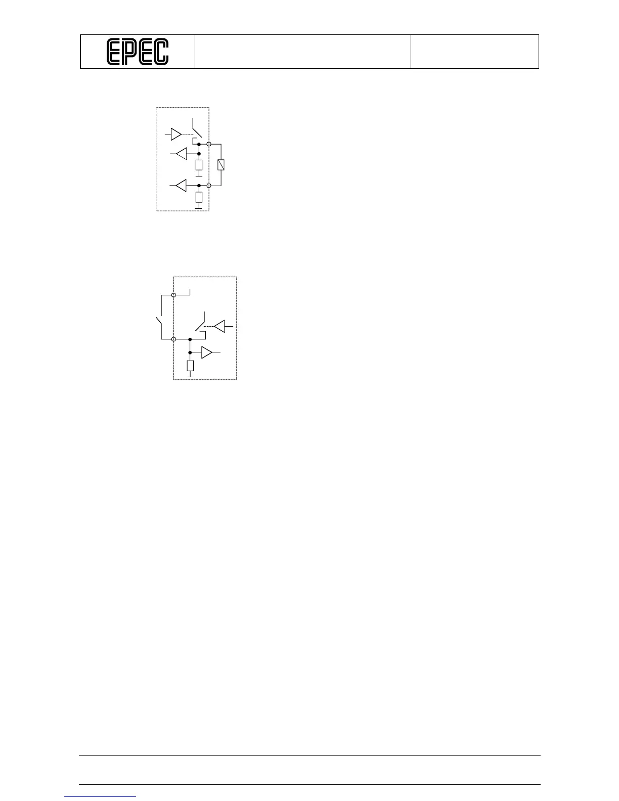
Connection Principle
A pin where the lower wire of the load is connected is current measuring feedback. This
illustrates the normal way to connect loads when load current measurement is desired.
Connection Principle (when used as an input)
Note 1: PWM capable outputs are divided into six groups. All outputs in the same group share
the same PWM frequency (default value 140 Hz)
Note 2: Violating this rating may lead to system not recognizing all input state transitions
Note 3: These parameters depend on software cycle time
Note 4: t
C
denotes software cycle time
+24V
Module
Load
+24V/+12V
Module
+24V