1
EMP-9000/8000
SEIKO EPSON Revision:A
Contents
Chapter 1 Product general
1.1. PRODUCT GENERAL............................................................................1-2
1.2. PART NAME...........................................................................................1-3
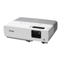
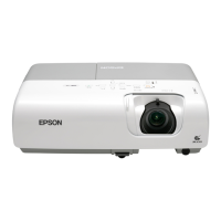
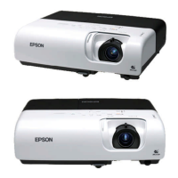
1.2.1. Outside View of Main Frame...........................................................1-3
1.2.2. Inside view of main frame................................................................ 1-5
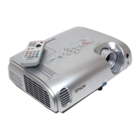
1.2.3. Outside View of Remote Controller................................................. 1-6
1.3. MAIN COMPORNENT............................................................................1-7
1.4. SPECIFICATIONS................................................................................1-12
1.4.1. Main unit specifications .................................................................1-12
1.4.2. Accessory specification................................................................. 1-13
1.5. INTERFACE SPECIFICATION.............................................................1-15
1.5.1. Computer 1 (The picture input of analogue RGB from Computer) 1-15
1.5.2. Audio 1 (The voice input from computer)......................................1-15
1.5.3. Audio Out ...................................................................................... 1-16
1.5.4. Monitor Out.................................................................................... 1-16
1.5.5. S-Video.......................................................................................... 1-16
1.5.6. Video In / Audio L/R ......................................................................1-17
1.5.7. Mouse / Com 1/2...........................................................................1-17
1.5.8. Remote.......................................................................................... 1-18
Chapter 2 Theory of operation
2.1. Hardware Configulation .......................................................................... 2-2
2.1.1. Process Outline............................................................................... 2-3
2.1.2. Electrical System.............................................................................2-4
2.1.3. Optical System Connections (Optical Engine) ................................2-4
2.2. Filter unit / Safety switch......................................................................... 2-7
2.2.1. Filter unit circuit block...................................................................... 2-7
2.3. Power Supply Unit ..................................................................................2-8
2.3.1. Power supply unit circuit block ........................................................2-8
2.4. Ballast unit ............................................................................................2-11
2.5. Main Board Assy Unit ...........................................................................2-13
2.6. Driver Board Assy................................................................................. 2-19
2.7. AU Board Assembly.............................................................................. 2-22
2.8. IF Units.................................................................................................. 2-23
2.9. Connector Boarrd U Assembly / Connector Board L Assy ...................2-26
2.10. RC Receptor Board Assembly............................................................2-28
2.11. Speaker Unit ....................................................................................... 2-29
2.12. Light Guide Unit ..................................................................................2-30
2.13. Lamp Inner Housing............................................................................ 2-32
2.14. Sensor / Switch...................................................................................2-36
2.14.1. Interlock Switch (A part of filter unit )...........................................2-37
2.14.2. Safety Switch...............................................................................2-38
2.14.3. Thermistor and temperature sensor operation............................2-38
2.15. Fan Operation.....................................................................................2-40
2.16. LED indicator ......................................................................................2-43
2.17. Operation Panel (Upper Case Unit)....................................................2-44