Do you have a question about the Epson EMP-8000 and is the answer not in the manual?
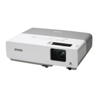
Detailed description of the EMP-9000/8000 multimedia projector and its key features.
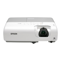
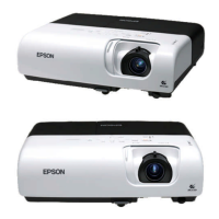
Identification and location of various external parts of the projector.
Illustrates the external view of the projector's main frame.
Shows the internal layout of the projector's main frame.
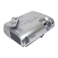
Depicts the front and back views of the projector's remote controller.
Visual identification of the projector's primary internal components.
Comprehensive technical specifications for the projector.
Detailed specifications for the main projector unit, including optical and audio features.
Specifications for included accessories like remote control and cables.
Details on all input and output interfaces, including pin assignments.
Specification for the Computer 1 analog RGB picture input interface.
Specification for the Audio 1 voice input interface.
Specification for the 3.5mm stereo mini-jack audio output.
Specification for the monitor output interface.
Specification for the S-Video input interface.
Specification for Video In and Audio L/R interfaces.
Specification for Mouse and Communication port interfaces.
Specification for the 3.5mm stereo mini-jack remote control interface.
Overview of the projector's hardware architecture, detailing optical and electrical systems.
Step-by-step explanation of signal processing and light path within the projector.
Description of electrical units and their functions within the projector.
Explanation of optical system component connections and integrated function.
Details on the filter unit, AC interlock, and safety switch functions.
Circuit diagram for the filter unit, including AC interlock and safety switch.
Explanation of the power supply unit's structure, function, and specifications.
Circuit diagram detailing the power supply unit's internal functions.
Description of the ballast unit's role in lamp power regulation.
The central control unit responsible for projector operations.
Converts R/G/B signals and controls display image via electrical correction.
Handles audio amplification and speaker connections for sound output.
Manages interface connectors and audio controller for external device connectivity.
Connects exhaust fans and receptor board assemblies.
Detects infrared signals from the remote controller for projector operation.
Internal speakers for audio output and their connection management.
Disperses and uniforms light from the lamp for the optical system.
Houses the light source lamp and related control connectors.
Details various sensors and switches for safety and operational protection.
Description of the interlock switch for safety during lamp access.
Description of the thermal safety switch for overheat protection.
Operation of thermistors and temperature sensors for monitoring and control.
Explanation of the function and control of the projector's cooling fans.
Description of status indications provided by the operation, lamp, and temperature LEDs.
Details the function of the physical operation panel and its switches.
General procedures and safety precautions for disassembling and reassembling the projector.
Step-by-step guide for dismantling the main unit, including a flowchart.
A visual flowchart illustrating the sequence of disassembly steps for the main unit.
Procedure for removing the lamp cover unit.
Procedure for removing the lamp inner housing.
Procedure for removing the air filter.
Procedure for removing the front case.
Procedure for removing the projector lens.
Procedure for removing the upper case unit.
Procedure for removing the main board assembly unit.
Procedure for removing the IF unit.
Procedure for removing the IF panel unit.
Procedure for removing the optical engine assembly.
Procedure for removing the power supply unit.
Procedure for removing the ballast unit.
Procedure for removing the filter unit.
Procedure for removing the LAMP thermistor.
Procedure for removing the safety switch.
Procedures for aligning optical components like head unit, prism, and light guide.
Explanation of necessary electrical corrections for the driver board.
Important warnings and precautions to observe during field maintenance.
Preliminary steps and checks before initiating troubleshooting.
List of necessary tools and accessories for effective troubleshooting.
Guidance on identifying and replacing common field-replaceable parts.
A flowchart to guide the initial steps in diagnosing and resolving projector issues.
Troubleshooting steps related to the external appearance and condition of the projector.
Troubleshooting steps related to internal cable connections.
Troubleshooting steps for issues related to power on/off functionality.
Troubleshooting steps for problems with display and picture quality.
Troubleshooting steps for issues related to audio output.
Troubleshooting steps for problems with the operator control panel.
Troubleshooting steps for issues with the remote controller.
Troubleshooting steps for other miscellaneous problems like noise or overheating.