Maintenance 4. Cable
96 G3 Rev.14
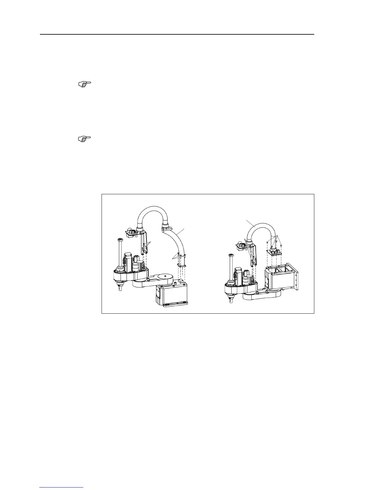
Disconnect 11 connectors on the Arm side.
Connectors X21, X22, X31, X32, X33, X41, X42, X61, X221, X231, X241
X61 is connected to the battery board.
Be sure to keep the connectors of the battery board connected at cables replacement.
Otherwise, the
Joint #2, #3, and #4 motors will lose position
data and the calibration
must be executed agai
-sub cable, air tubes, and connector of the brake release switch from
Mounting screws for the D
-sub cable are very small. Be sure to keep the screws.
Press the ring on the fitting and pull out the air
observe the connection for connecting the disconnected parts after
Remove the mounting screws for the cable unit and remove the unit from the
Manipulator.

 Loading...


