Maintenance 9. Replacing Arm #1
148 G3 Rev.14
Prepare the spare Arm #1 and mount the mechanical stop.
Base side Table Top M8×10 1 unit (Bottom surface, Center, 1 point)
Multiple M8×10 2 units (Top surface, Center, 2 points)
Arm #2 side M8×10 2 units (Top surface, Center, 2 points)
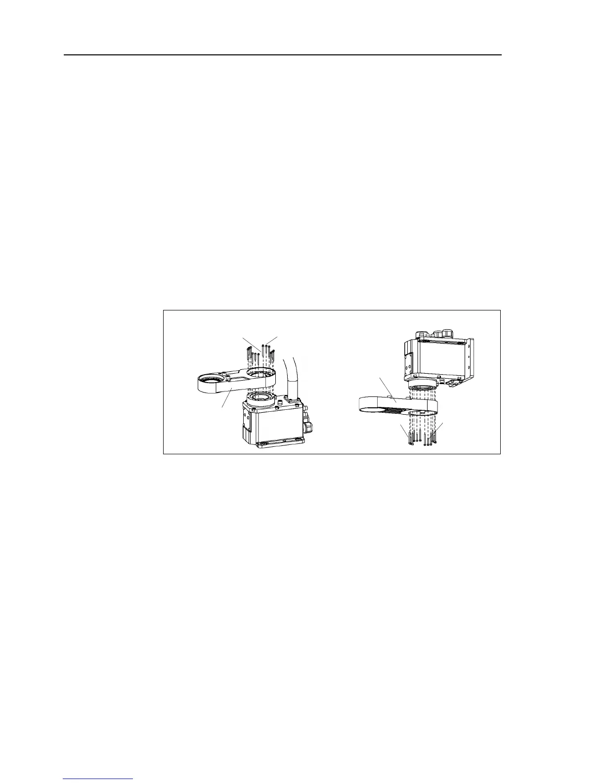
Insert the base side of Arm #1 to the harmonic drive of the base.
In case of Multiple mounting type,
Insert the O ring into the chase in the Joint #1
mounting surface of Arm #1 before
Apply a small amount of grease for the reduction gear to the O ring.
Fit with the space for the screws head of harmonic drive on Arm #1 side.
screws and mount the Arm #1 unit with specified torque.
M3 tightening torque: 3.0 N⋅m (30.6 kgf⋅cm)
Use 35 mm screws to all side and the middle one in each side is 20 mm.
Do not use the screws of different length. Otherwise, it causes a malfunction.
Table Top mounting Multiple mounting
There is an O ring groove in the Arm #2 mounting part on Arm #1 side. Insert an
O ring in the groove.
Apply a small amount of grease on the O ring.
Insert the Arm #2 side on Arm
#1 to the harmonic drive of Arm #2.
Fit with the space for the screws head of harmonic drive on Arm #2 side.

 Loading...


