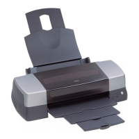
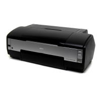
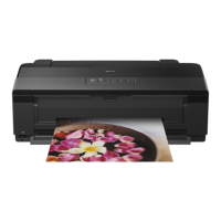
EPSON Stylus Photo 1390/1400/1410 Revision B
DISASSEMBLY AND ASSEMBLY Disassembly/Assembly Procedures 98
4.2.6.5 Carriage Shaft and Carriage Unit
1. Remove the APG Assy. See Section 4.2.6.4 on page 96.
2. Turn the PG Cam (Right) around so that any mark other than PG++ comes to the
bottom.
Figure 4-58. Setting the PG Cam
3. Remove the two C.B.S. 3x6 screws that secure the Frame Support Plate (Left), and
remove it.
Figure 4-59. Removing the Left Frame Support Plate
4. Remove the foot of Left PG Torsion Spring from Tab A, and release the coil
section from Tab B to remove Left PG Torsion Spring from the Main Frame.
Figure 4-60. Removing the Left PG Torsion Spring
PG Cam (Right)
1
2
2) C.B.S. 3x6
(8±1 kgf.cm)
Tab
Tabs
Left Frame Support Plate
Paper EJ Frame Assy
Cutout
Insert the Left Frame Support Plate into the cutout of the Main
Frame. See Figure 4-59.
Align the two tabs on the Main Frame and the tab on the Paper
EJ Frame Assy with the three positioning holes on the Left
Frame Support Plate. See Figure 4-59.
Align the tab (rear side) of the Left Frame Support Plate with
the outside of the Left CR Shaft Mounting Plate. See Figure
4-59.
Tighten the screws in the order shown in Figure 4-59.
Left PG Torsion Spring
Tab A
Tab B

 Loading...


