EPSON Stylus Photo RX585/RX595/RX610 Revision B
Disassembly and Assembly Overview 62
4.1.6 Disassembly and Reassembly Procedure
The flowchart below shows step-by-step disassembly procedure for Stylus Photo RX585/595/610. When disassembling each component, refer to the page indicated for the relevant
component.
Flowchart 4-1. Disassembly Procedure
*
1
For replacement of the Printer Mechanism Assy, install not only the
housings but also the following parts when installing the new Printer
Mechanism Assy.
• Intermediate Gear (26.5) (p.83)
• PF Encoder Scale (p.83)
•PF Motor (p.83)
• ASF Assy (p.85)
• Printhead (p.73)
• Head FFC Assy (p.91)
*
2
By using the special tool, the Printhead can be replaced without removing
the Middle Housing. (See p.73)
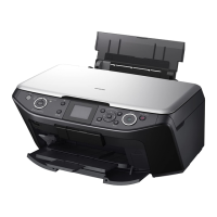
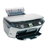
The color and shape of the printer illustrated in this manual may
differ from the final product.
Panel Assy
(p.63)
Middle Housing Assy
(p.70)
Scanner Unit
(p.65)
Printer Mechanism
(p.76)
Main Board Assy /
Case Open Sensor
(p.66)
Waste Ink Tray Assy
(p.69)
CR Motor
(p.88)
PF Motor
(p.83)
Stacker Assy
(p.81)
PF Scale and PF Encoder
(p.83)
Linear Scale
(p.75)
APG Assy
(p.87)
Carriage Assy
(p.89)
Power Supply Board
(p.80)
I/S Assy
(p.84)
ASF Assy
(p.85)
Paper Guide Front Assy
(p.93)
Upper Paper Guides
(p.92)
Waste Ink Pads
(p.80)
Eject Frame Assy
(p.91)
Printhead
(p.73)
*
2
Scanner Housing
(p.77)
CR Motor Unit
(p.79)
CIS Unit
(p.78)
*
1
Paper Guide Front Assy
(p.93)
I/S Assy
(p.84)

 Loading...


