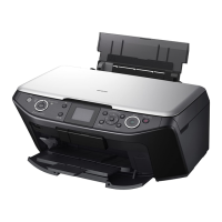
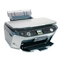
EPSON Stylus Photo RX585/RX595/RX610 Revision B
Disassembly and Assembly Removal of Exterior Parts 63
4.2 Removal of Exterior Parts
4.2.1 Panel Assy
1. Open the Scanner Unit, and remove the screws (x3) securing the Middle Cover
Assy. (Fig. 4-4)
2. Release the hooks (marked with Δ : x4) on the side of the Printer Mechanism to let
the Middle Cover rise, insert a bamboo spatulas whose tip is soft into the cut
portion at the front center to release the hook, and remove the Middle Cover Assy.
3. Release the hooks at the right and left ends from the direction of the back of the
panel to let the decorative panel rise, release all the hooks carefully and remove the
decorative panel.
4. Remove the screws (x2) securing the Panel Assy. (Fig. 4-5)
5. Disconnect the Cover Open Sensor connector from the Panel Board. (Fig. 4-6)
6. Lift the Panel Assy, and disconnect the connectors (CN23 and CN22) from the
Main Board.
7. Peel the FFC (CN23) of the Panel Board from the Main Board Assy, and remove
the Panel Assy. (Fig. 4-6)
Figure 4-4. Removing the Middle Cover Assy
Figure 4-5. Removing the Decorative Panel and Panel Assy
Figure 4-6. Removing the Panel Assy
After removing the decorative panel, take care that the LCD
surface is kept free from scratches or dust and dirt.
When installing the decorative panel, observe the following
instructions:
Make certain that the back of the panel window and the LCD
face are free from dust and dirt.
Secure the decorative panel with Double-stick tape.
C.B.P-TITE 3x10 (x3)
Torque : 0.6±0.1N
·m
Hook (x4)
Middle Cover Assy
Hook (x3)
Panel Assy
C.B.P-TITE 3x10 (x2)
Torque : 0.6±0.1N
·m
Unhook (x10)
Decorative panel Double-stick tape
CN23
CN22
Double-stick tape
Double-stick tape
CN23
CN22
Cover Open Sensor connector

 Loading...


