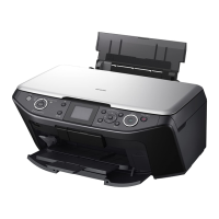
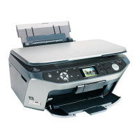
EPSON Stylus Photo RX585/RX595/RX610 Revision B
Disassembly and Assembly Disassembly of Housing Lower Assy 80
4.4 Disassembly of Housing Lower Assy
4.4.1 Waste Ink Pads
1. Remove the Printer Mechanism (p.76)
2. Remove Waste Ink Pads (x2) from the Housing Lower. (Fig. 4-46)
4.4.2 Power Supply Board
1. Remove the Printer Mechanism (p.76)
1. Remove the screw securing the P/S Assy, and remove it from the Housing Lower.
(Fig. 4-47)
2. Remove the screw, and remove the P/S Cover. (Fig. 4-48)
3. Disconnect the connector, and remove the Power Supply Board.
Figure 4-46. Removing the Waste Ink Pads
Figure 4-47. Removing the P/S Assy
Figure 4-48. Removing the Power Supply Board
When removing the Waste Ink Pads, take due care not to stain
any surrounding objects with waste ink.
Place the Waste Ink Pads (x2) by pushing them along the cut
portions until they are all the way seated and make sure that
they are free from floating.
A D J U S T M E N T
R E Q U I R E D
On the occasion of replacing a part with a new one, replace all the
specified parts with new ones and clear the counter value after
assembly.
5.2 Adjustment by Using Adjustment Program (p.101)
Before installing the P/S Cover, route the connector cable so
that it is led through the position shown in the figure.
Install the P/S Assy in the Housing Lower by installing the AC
connector side first and set the ferrite core.
A D J U S T M E N T
R E Q U I R E D
When the Power Supply Board has been replaced with a new one,
refer to the following section and perform the necessary
adjustments.
5.2 Adjustment by Using Adjustment Program (p.101)
No need to
replace
Waste Ink Pad
Waste Ink Pad Tray
(Housing Lower)
P/S Assy
C.B.P-TITE 3x10
Torque : 0.6±0.1N
·m
After installing the ferrite core, stick the acetate tape (50 mm long).
Lead out the connector here
P/S Cover
C.B.P-TITE 3x10
Torque : 0.6±0.1N
·m
Disconnect the connector
Power Supply Board

 Loading...


