VT6L Maintenance 18. Controller Unit
VT series Maintenance Manual Rev.2 155
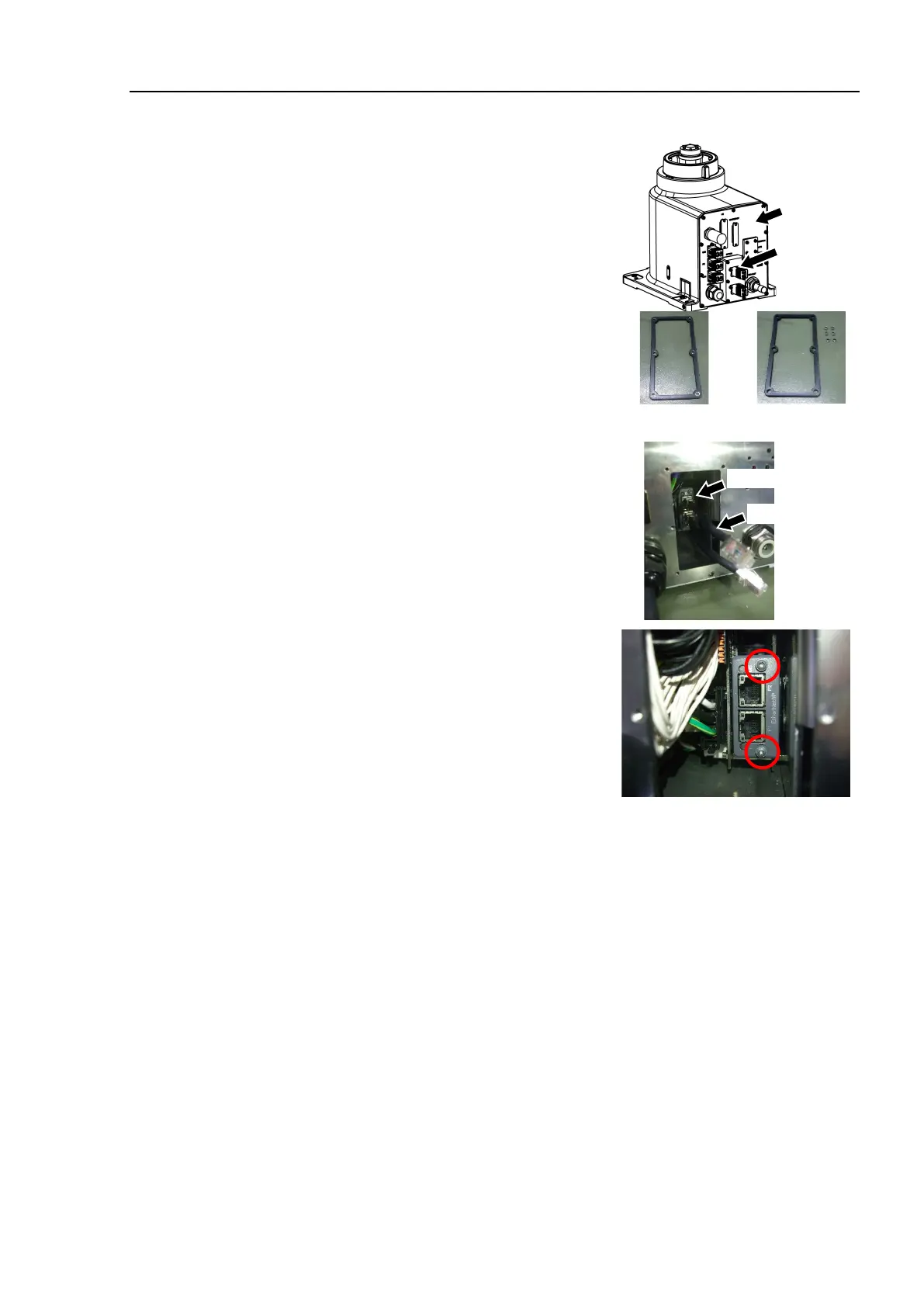
I/O Module
Removal
Protection model
EtherCAT,
EtherNet IP,
PROFINET
Turn OFF the Manipulator.
Remove the bolts which secure the optional
block to the connector plate.
Hexagon socket head bolts:
(supplied with the module.)
6-M3×30 (with seal washer)
Remove the two relay cables from the
conector on the optional block side.
Remove the gasket and spacers.
Disconnect the relay cable from the fieldbus
I/O module.
Loosen the screws by using the supplied hex
lobe wrench.
Remove the fieldbus I/O module.
The module can be removed by pulling the screws forward with the screws
loosened.
Install the optional slot cover, gasket, and spacers.
Hexagon socket head bolts: 6-M3×8 (with seal washer.)
Tightenning torque: 2.0 ± 0.1N·m
Be sure to embed the seal washers (supplied with the module) when tightening
with hexagon socket head bolts.
If the seal washers are not embedded, water protection performance may not be
ensured.
Make sure that there is no scratch and dust on the gasket mounting surface.
If the gasket is damaged or dusty, water protection performance may not be
ensured.

 Loading...


