VT6L Maintenance 18. Controller Unit
156 VT series Maintenance Manual Rev.2
CC-Link
I/O Module
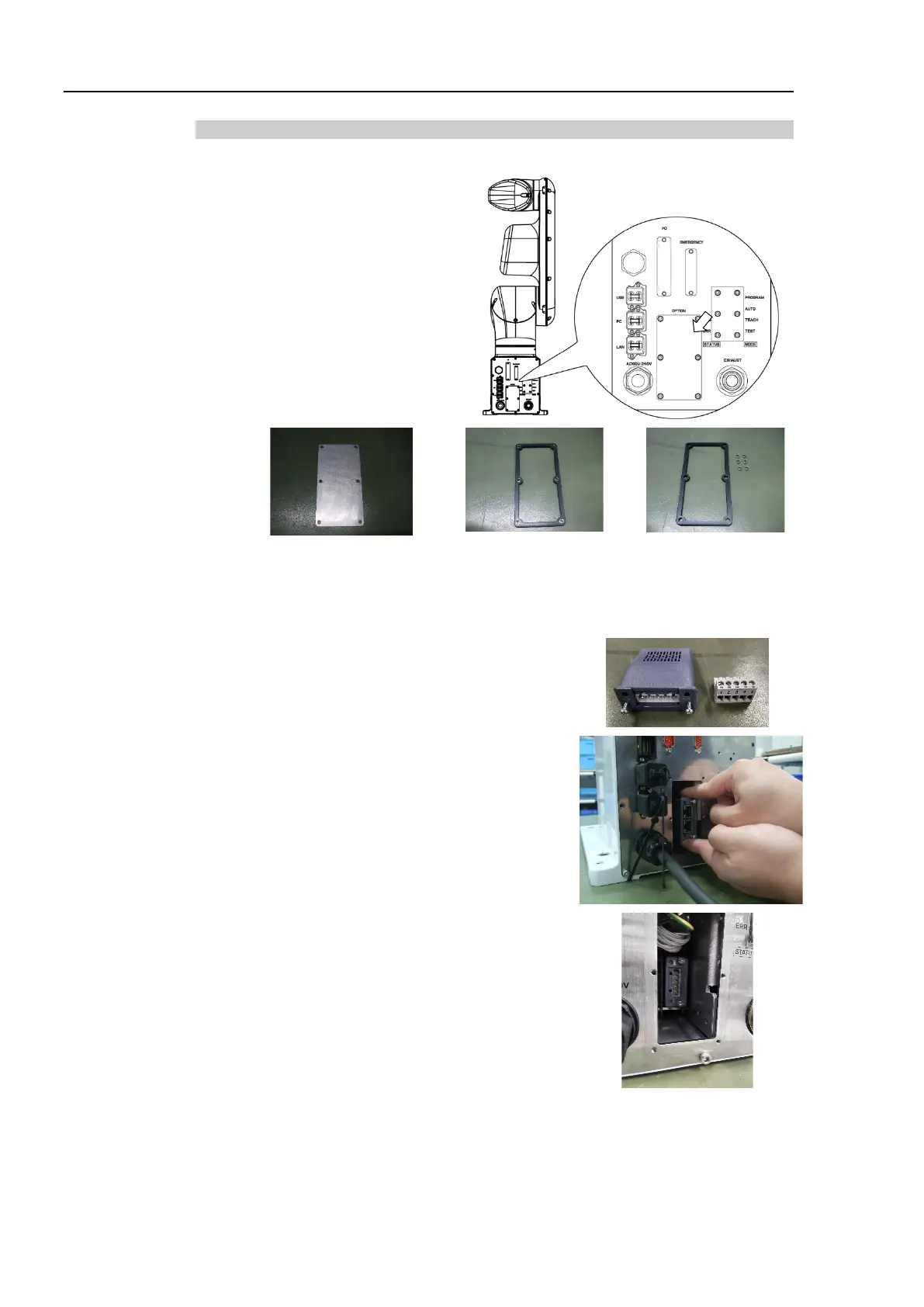
Installation
Protection model
CC-Link
Turn OFF the Manipulator.
Remove the following parts on
the rear side of the Manipulator.
Optional slot cover
Gaskets
Spacers
Hexagon socket head bolts
: 6-M3×8
Note that the spacers may fall out when removing the gasket.
Be careful not to damage the mounting surface of the gasket. If the surface is
damaged, water protection performance may not be ensured.
Remove the connector which installed on the
fieldbus I/O module.
Insert the fieldbus I/O module into the optional
slot.
Make sure that the fieldbus I
/O module is
completely inserted. Move the module up and
down lightly and check whether the module is
fixed in place.

 Loading...


