VT6L Maintenance 18. Controller Unit
VT series Maintenance Manual Rev.2 157
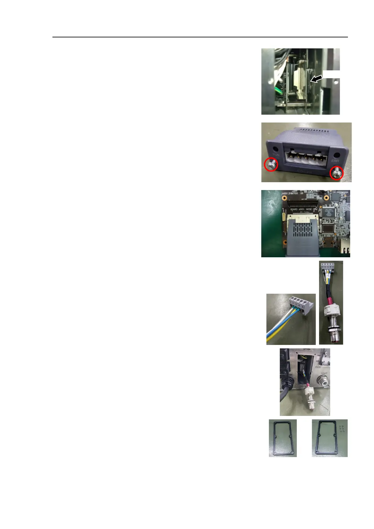
If you touch the SD card while installing the
fieldbus I/O module, it may come out.
Manipulator (Controller part) will not operate
properly if the SD card is not inserted.
(5)
Tighten the screws by using the supplied hex
lobe wrench until the fieldbus module is fixed
completely.
Tightening torque: 0.25 N·m
Install the connector (supplied with the fieldbus
I/O module) to the relay cable terminal which
installed to the optional block.
1: Shield wire
2: White wire
3: Yellow wire
4: Blue wire
Connect the supplied connector to the fieldbus
I/O module.
Install the spacers to the gasket.
(6 spacers: the gasket is supplied with the
module.)
Spacers
Spacers

 Loading...


