VT6L Maintenance 18. Controller Unit
VT series Maintenance Manual Rev.2 167
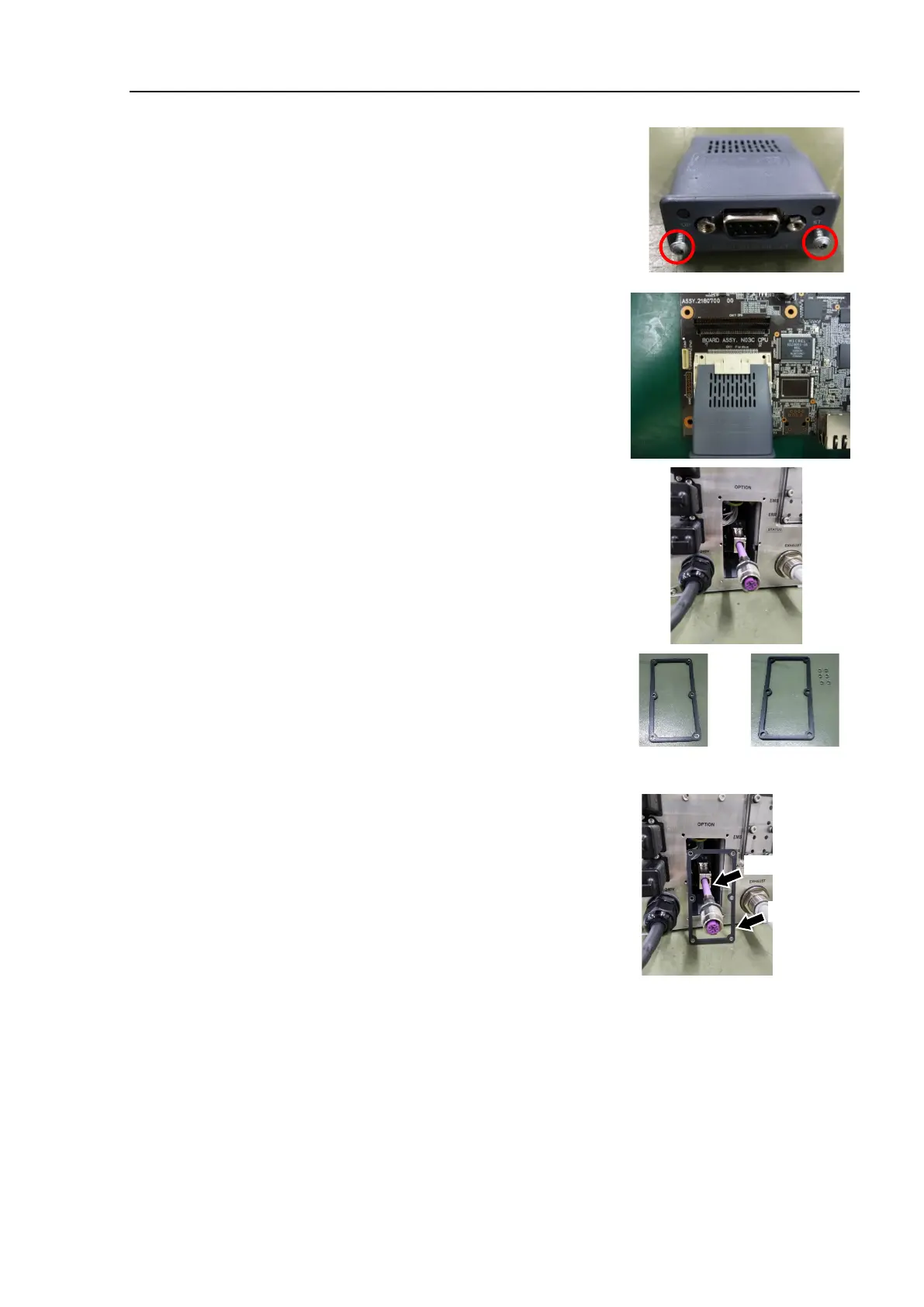
(4)
Tighten the screws by using the supplied hex
lobe wrench until the fieldbus module is fixed
completely.
Tightening torque: 0.25 N·m
Connect the D-sub connector to the fieldbus
I/O module.
Tighten the two securing screws.
Tightening torque: 0.25 N·m
Install the spacers to the gasket.
(6 spacers:
the gasket is supplied with the
module.)
Pass the relay cable through the gasket.
Temporarily secure the relay cable connector to the optional block with a nut
(M12).

 Loading...


