VT6L Maintenance 8. Cable
VT series Maintenance Manual Rev.2 47
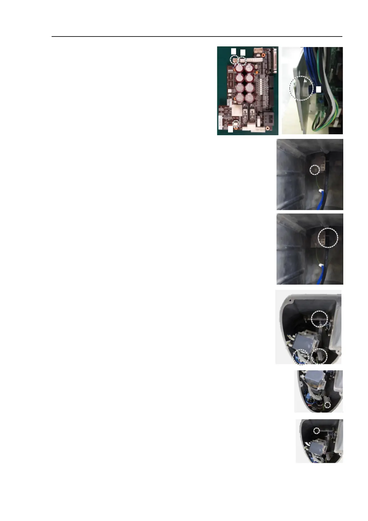
the following
connectors of the Controller U
nit.
A: Power cable connector
B: Signal cable connector
C: LED connectors × 2
7)
Remove the ground wire terminal
s inside the base.
Cross recessed head screws: M4×6
the wire tie bound to the plate inside the base.
Wire tie: AB150
Cut off the wire ties bound inside the Arm #1.
Wire ties : AB150 × 2
AB100 × 1
Remove the ground wire terminals
of Arm #1.
Cross recessed head screws: 2-M4× 6

 Loading...


