VT6L Maintenance 8. Cable
VT series Maintenance Manual Rev.2 55
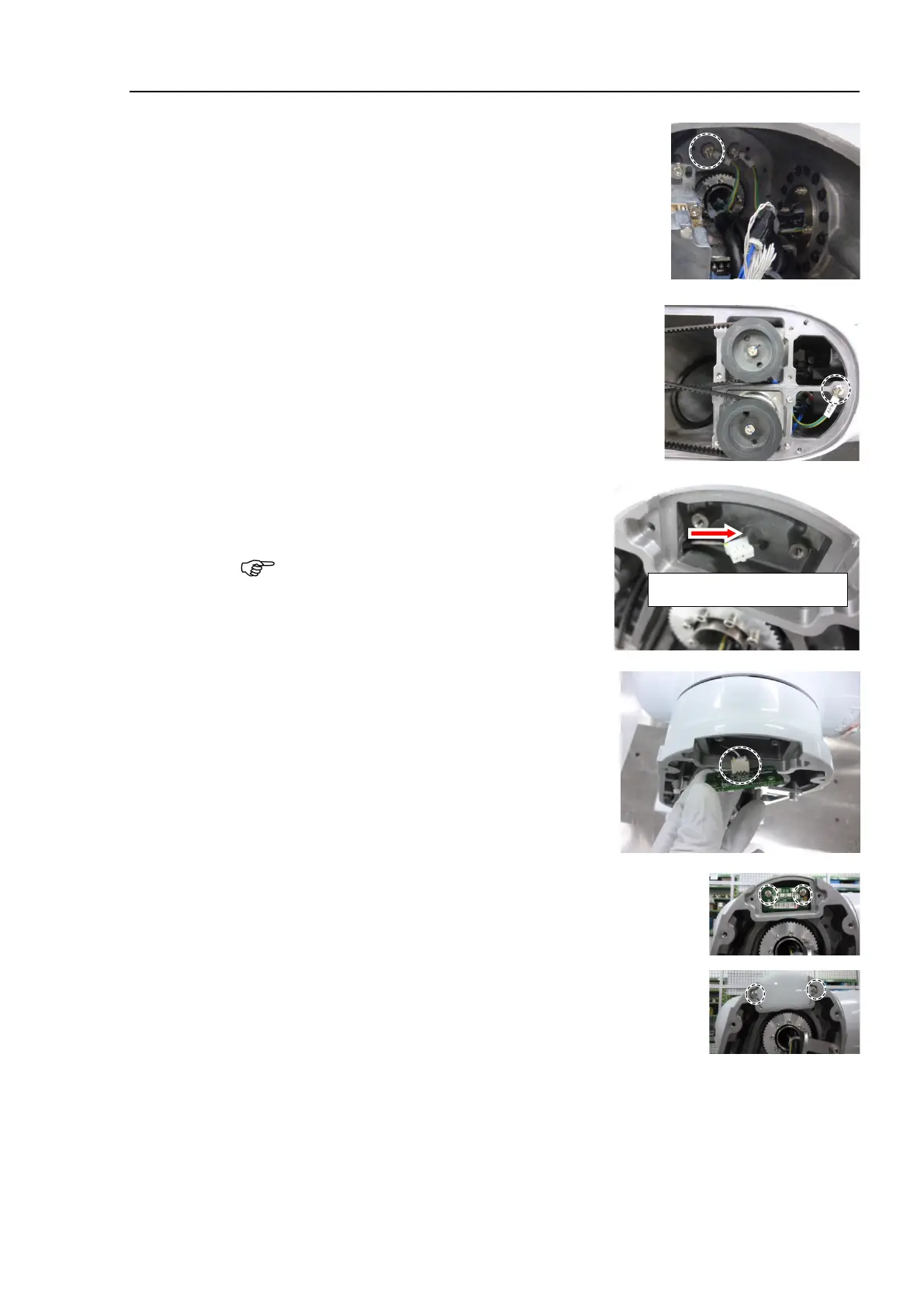
the ground wire between the Arm #3 and the Arm #4.
Cross recessed head screws: 2-M4×6
Tightening torque: 2.0 ± 0.1 N·m
Arm #3 side:
Ground wire terminal marked “ARM3” on the wire
marker.
Arm #4 side:
Ground wire terminal marked “ARM4” on the
marker.
the LED cable connector to the
opening of the end of Arm #2.
You can pass the connector through the
opening easily by using
the wire tie.
the LED cable connector to the LED
Connectors: LED_CN1
Cross recessed head screws: 2-M3×6
Tightening torque: 0.45 ± 0.1 N·m
the light guide plate.
Cross recessed head screws: 2-M3×10
Tightening torque: 0.45 ± 0.1 N·m

 Loading...


