VT6L Maintenance 9. Joint #1
72 VT series Maintenance Manual Rev.2
Pass the following cables through a new Joint #1 timing belt.
Power cable
Signal cable (for motor)
LED cable
Ground wire
Mount the Joint #1 motor unit.
Reference: 9.1 Replacing Joint #1 Motor
Joint #1 Motor Installation (2) through (8)
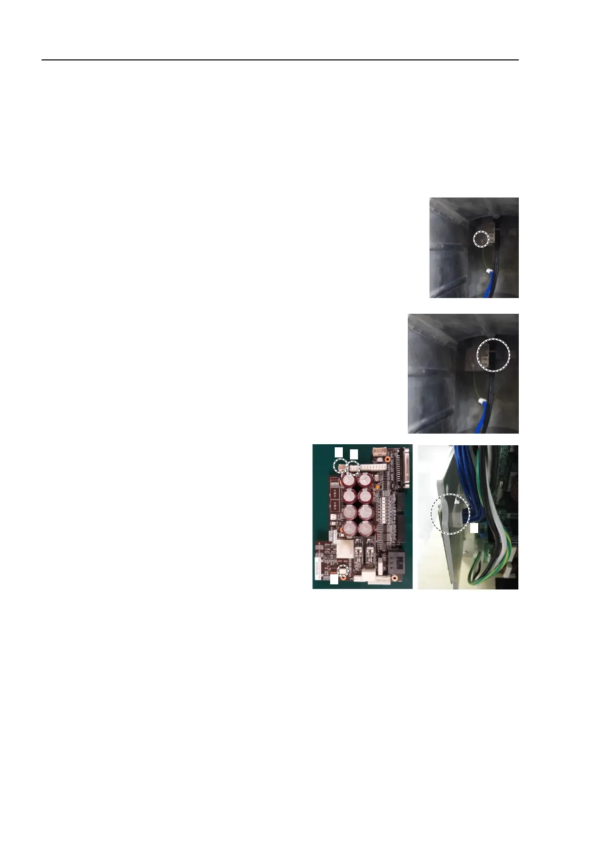
Connect the ground wire terminals inside the base.
Cross recessed head screws: M4×6
Tightening torque: 2.0 ± 0.1N m
Pass the wire tie through the hole on the plate inside the
base.
Bind the following cables with the wire tie.
Wire tie: AB150
Power cable
LED cable
Signal cable (for motor)
Ground wire
Connect the following connectors
to the Controller Unit.
A: Power cable connector
B: Signal cable connector
C: LED connectors × 2

 Loading...


