VT6L Maintenance 9. Joint #1
VT series Maintenance Manual Rev.2 71
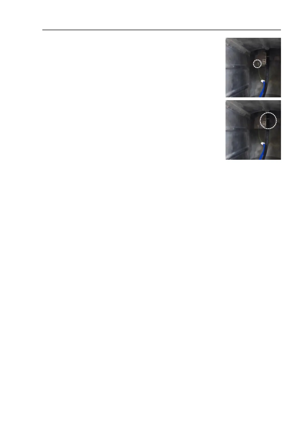
terminals inside the base.
Cross recessed head screws: M4×6
Cut off the wire tie bound to the plate inside the base.
Wire tie: AB150
Remove the Joint #1 motor unit.
Reference: 9.1 Replacing Joint #1 Motor
Joint #1 Motor Removal (3) through (7)
Pull out the following cables from the Arm #1 side and remove the Joint #1 timing belt.
Power cable
Signal cable (for motor)
LED cable
Ground wire

 Loading...


