5 OPERATION
0463 479 001
- 21 -
© ESAB AB 2017
Secure the return cable's contact clamp to the workpiece and ensure that there is good
contact.
5.3 Polarity change
The power source is delivered with the polarity changeover cable connected to the positive
terminal. Some wires, e.g. self-shielded cored wires, are recommended to be welded with
negative polarity. Negative polarity means that the polarity changeover cable is connected to
the negative terminal and the return cable to the positive terminal. Check the recommended
polarity for the welding wire you want to use.
The polarity can be changed by moving the polarity changeover cable to suit the applicable
welding process.
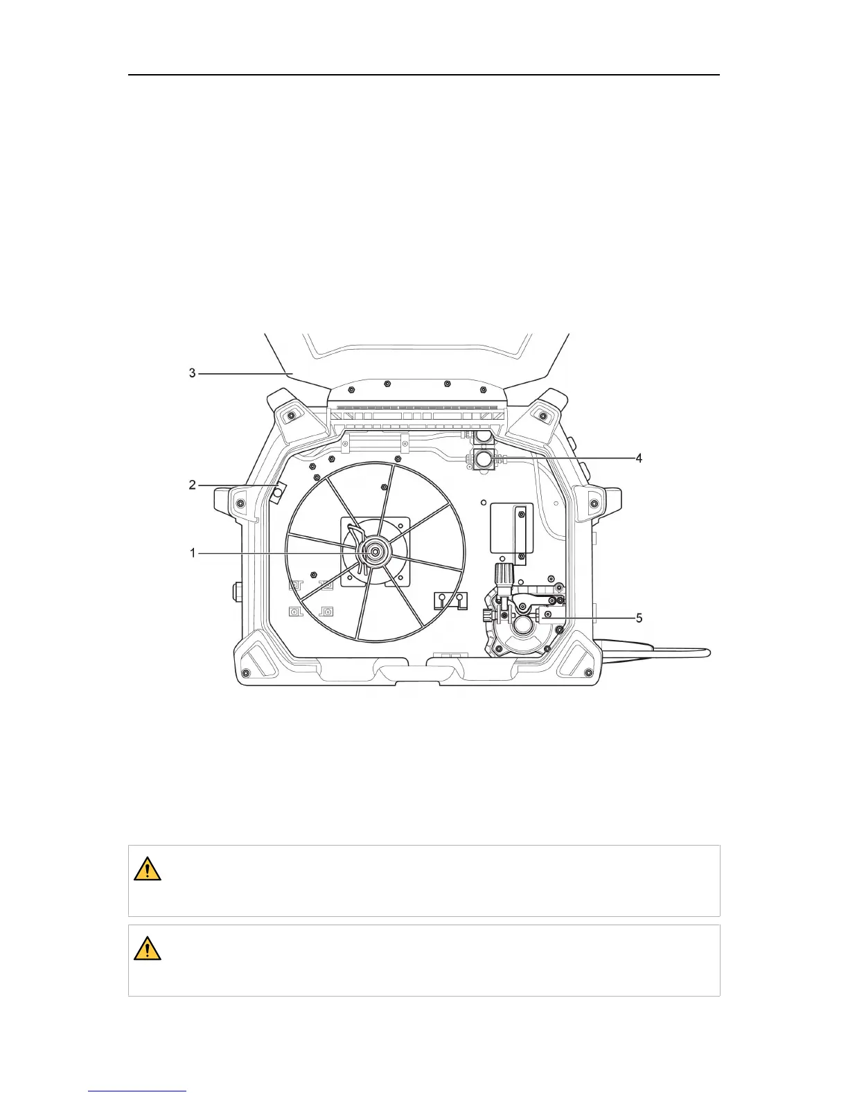
Drive system diagram
1. Spool hub 4. Gas valves
2. Circuit breaker 5. Wire feed mechanism
3. Opening side cover
5.4 Inserting and replacing wire
EMP235ic and EM235ic will handle bobbin sizes of 4in. (100 mm), 8in. (200 mm) and 12in.
(300mm). See TECHNICAL DATA chapter for suitable wire dimensions for each wire type.
WARNING!
Do not place or point the torch near the face, hand, or body as this may result in
personal injury.
WARNING!
Risk of crushing or pinching when replacing the wire spool! Do not use safety
gloves when inserting the welding wire between the feed rollers.



 To Next Page