5 OPERATION
0463 933 001
- 16 -
© ESAB AB 2023
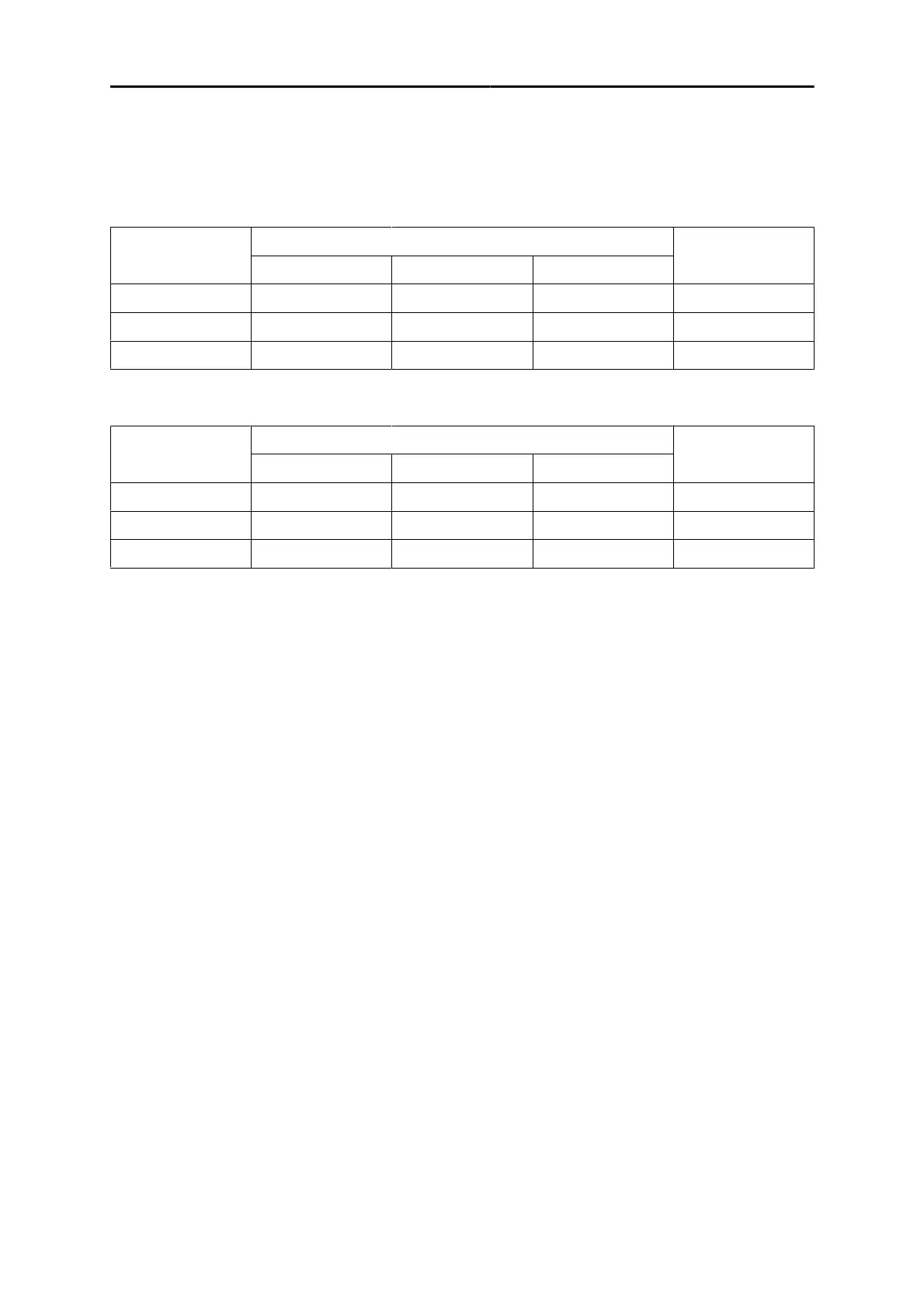
5.2 Recommended maximum current values for
connection cables set
Recommended maximum welding current values for the welding/return cable(copper) at an
ambient temperature of +25°C and normal 10minutes cycle
Cable size mm
2
Duty cycle
Voltage
drop/10m
100% 60% 35%
50 285A 320A 370A 0.352V/100A
70 355A 400A 480A 0.254V/100A
95 430A 500A 600A 0.189V/100A
Recommended maximum welding current values for the welding/return cable(copper) at an
ambient temperature of +40°C and normal 10minutes cycle
Cable size mm
2
Duty cycle
Voltage
drop/10m
100% 60% 35%
50 250A 280A 320A 0.352V/100A
70 310A 350A 420A 0.254V/100A
95 375A 440A 530A 0.189V/100A
5.3 Connecting welding and return cables
The power source has two outputs, a positive welding terminal (+) and a negative welding terminal (-),
for connecting welding and return cables. The output to which the welding cable is connected depends
on the welding method or type of electrode used.
Connect the return cable to the other output on the power source. Secure the return cable's contact
clamp to the work piece and ensure that there is good contact between the work piece and the output
for the return cable on the power source.
• For MIG/MAG and MMA welding, the welding cable can be connected to the positive welding
terminal (+) or negative welding terminal (-) depending on the type of electrode used. The
connecting polarity is stated on the electrode packaging.
5.4 Polarity change
The power source is delivered with the polarity changeover cable connected to the positive terminal.
Some wires, e.g. self-shielded cored wires, are recommended to be welded with negative polarity.
Negative polarity means that the polarity changeover cable is connected to the negative terminal and
the return cable to the positive terminal. Check the recommended polarity for the welding wire you
want to use.
The polarity can be changed by moving the polarity changeover cable to suit the applicable welding
process.