45
G5 Flue Installation
The freestanding unit and flue system should be installed prior to the DF-Series fireplace being
installed (for horizontal termination for DFS730: see next page, section G6).
□ Place the freestanding unit in the correct
location, complying with
the clearances specified in the previous
section.
□ Remove 2 screws on each side of the fas-
cia just below the top panel and pull towards
you to remove the fascia.
□ Fix the DFS730 unit to the floor using the
four securing holes in each corner of the unit.
□ Refer to Section B3 for flexi flue
clearances.
□ Refer to section C of this installation
manual for minimum and maximum flue
lengths, restrictor settings for your installa-
tion, and all other flue information.
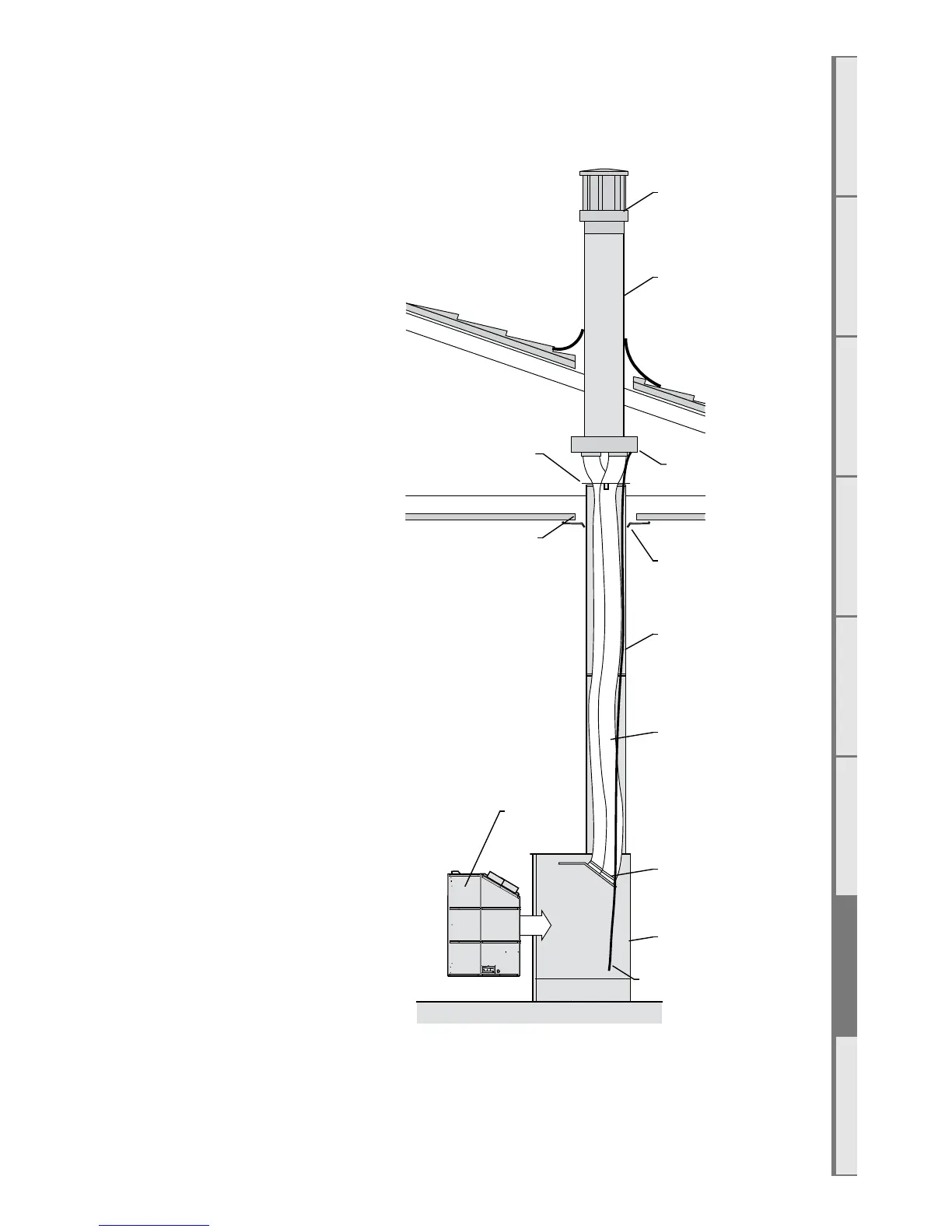
□ Run the black Ø230mm flue liner lengths
from the top of the freestanding unit until it
penetrates the Ø265mm ceiling hole.
□ Use the supplied Ceiling plate for
tidying the internal termination point of the
Ø230mm flue liner.
□ Run the 2x flexible flues down through the
Ø230mm flue liner and attach it to the Flue
Spigot Plate as per section C of this manual.
□ Run the power flue cable down through
the Ø230mm flue liner.
□ Open the flue liner rodent guard and close
around the flexi flue and power flue cable.
Rivet, screw or cable tie the open end to pre-
vent it from opening. Bend the two perpen-
dicular tabs down and screw into the flue liner
using a short self tapping screw. Note: Take
care when installing the rodent guard to not cause damage to the flexi flue or power flue cable.
□ Install flue termination as per section C of this manual
Note: Ensure a power supply is within 1m of the rear of the appliance.
Ceiling Ring
230mm
Flue liner
2x Flexible
ue
Duravent 5x8”
Rigid Direct-vent
ue
Rigid ue
Flexible ue clamped
to Flue Spigot Plate
DFS730
Fireplace
FS730 Freestanding
Unit
Flue Liner
Rodent Guard
Ø265 mm
Ceiling hole
Vertical Power Flue
Power Flue Cable