17
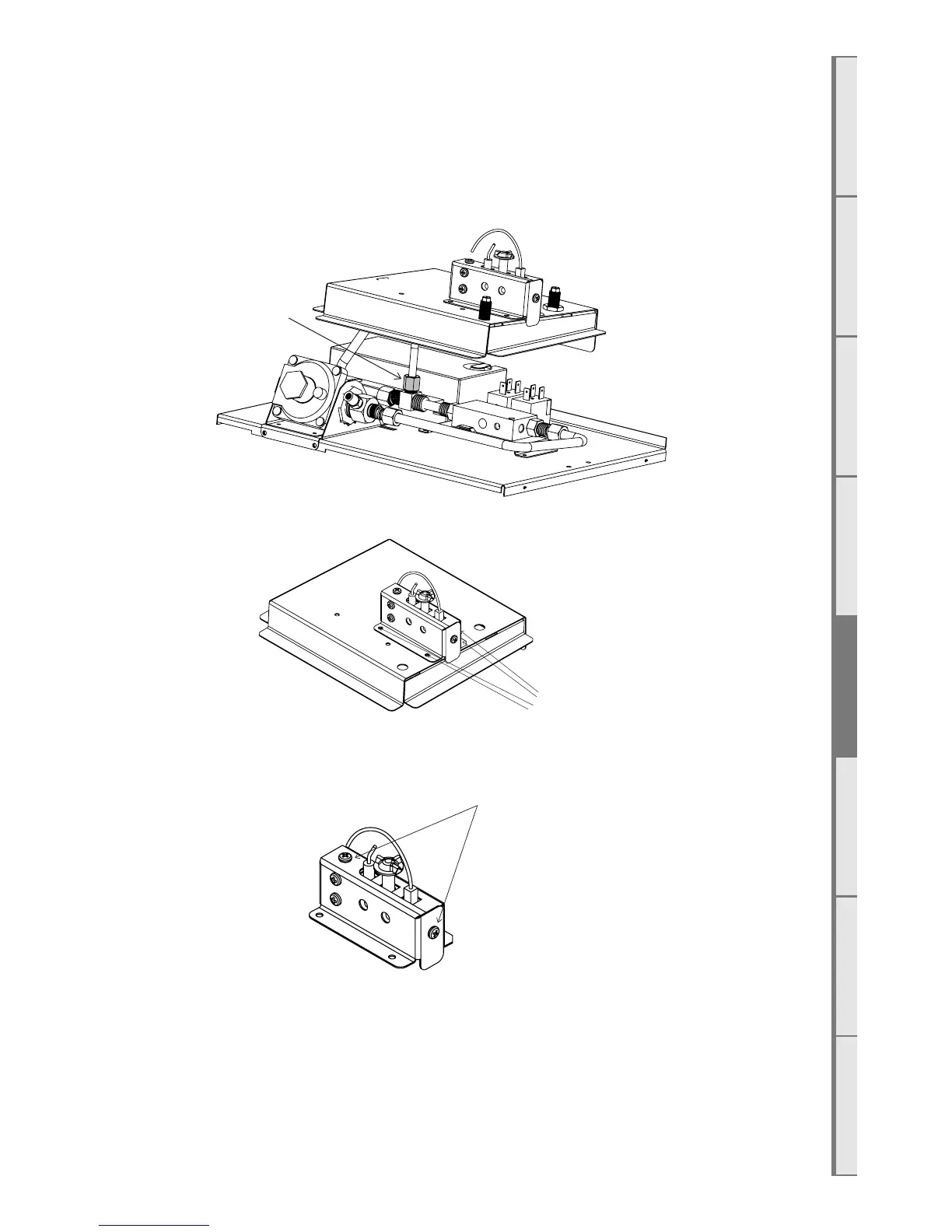
Step 5: Disconnect the blue and white wires between the pilot assembly and the rest of the tray. Use a
1/2” spanner to remove the nut from the pilot tube on the base of the tray.
Remove the brass nuts from the top of the gas pipes with a 5/8” spanner.
Lift the top pilot box assembly o of the lower engine.
Remove nut,
shaded grey
Step 6: Undo the 4 screws from the pilot box and remove the box assembly.
Remove 4
screws
Step 7: Remove the 2 screws from the pilot box and pull the cover o.
Remove 2 screws
Step 8: Remove the 2 machine screws from the pilot assembly to remove the electrode assembly from
the cover - they are held in by two bolts that can be removed with an 8mm spanner.