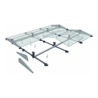
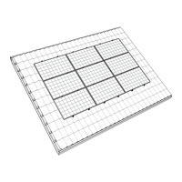
SEGMENT PLAN
BALLAST POSITIONSNAME
XXkg 2; XXXkg 3; XXXkg
DESCRIPTION
‘in the segment’
ballast position.
2
nd
ballast container added due to
higher ballast requirements for posi-
tions in the rst or single row.
2
nd
and 3
rd
ballast container added due
to higher ballast requirements for posi-
tions in the rst or single row.
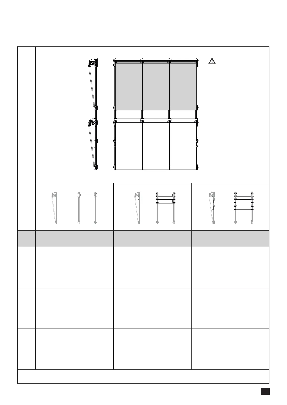
FIX / ALIGN.
Place ballast container on the high
base elements, and align them using
the slots (holder) and lugs (base
elements).
Position the 2
nd
ballast container using
the roof support adapters (spacers)
and screw it to the base proles.
Position the 2
nd
ballast container using
the roof support adapters (spacers) and
screw it to the base proles.
Position the 3
rd
ballast container using
the roof support adapters (spacers) and
screw it to the base proles.
WEIGHT DISTRIB.
Specied quantity of ballast in ballast
container 1.
Fill ballast container 1 to the maximum
level with ballast (do not stack) and
place the remainder of the specied
amount of ballast in ballast
container 2.
Fill ballast container 1 to the maximum
level with ballast (do not stack) and
place the remainder of the specied
amount of ballast in ballast container
2 and 3.
Note: For positions ‘in the segment’ no additional roof supports and roof support adapters are required for the place-
ment of the 2
nd
ballast container (optional)
30
Rev. 08.08.23 MANUAL FOR FLATFIX FUSION MOUNTING SYSTEM FOR FLAT ROOFS
7.4 Ballast configurations (contd.)
Single setup - 1/2
2.
1.
1.
3.
2.
1.
NOTE!
Always completely ll
ballast container 1 rst,
followed by ballast
container 2, and then
ballast container 3.
Do not distribute the
amount of ballast
between the containers
themselves.