35
Etac / Cross 5 / www.etac.com
1
1
5
5
1
1
5
5
1
1
5
5
A
3
1
2
5 mm
Cross 5
Cross 5 XL
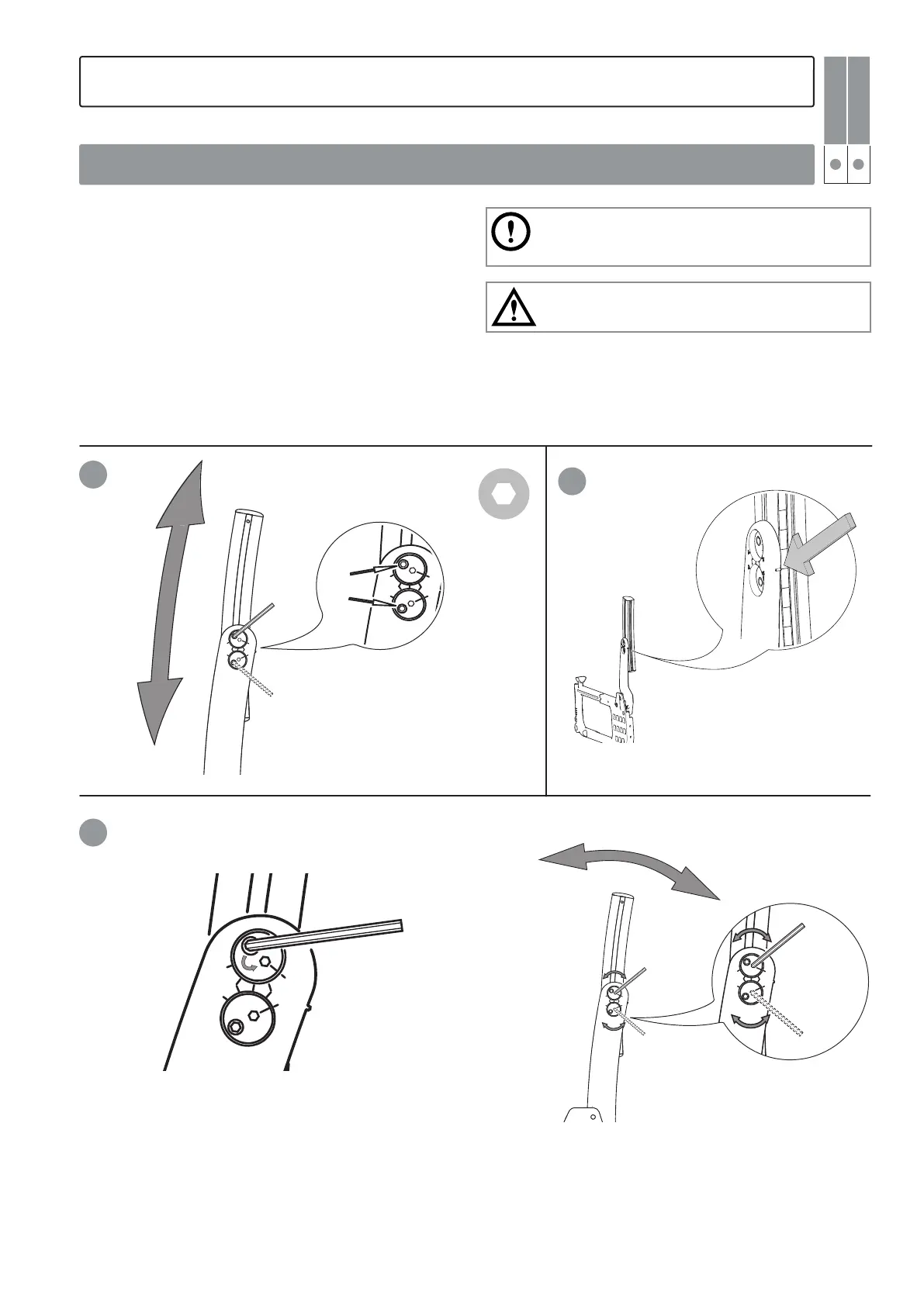
1. Loosen the locking screws (A) max. 1 turn.
2. Adjust the back support height using the graduation
and the marking on the lower back rod. Tighten the
locking screws max. 1/2 turn.
3. Place the Allen key in the selected (upper recommend-
ed) eccentric shaft’s locking screw and loosen it 1/2
turn. Move the Allen key to the eccentric shaft‘s key
handle and set the required lumbar angle.
4. Tighten the locking screws with 6 Nm.
We recommend that you start adjusting the lumbar
angle with the upper eccentric shaft. If a larger angle is
required, adjust the lower eccentric shaft as well.
Tipping risk! Always check the anti-tip function after
adjustments!
6. Settings back support 3A
Adjusting the back support height and lumbar angle (two eccentric shafts)