EVCO | 06.08.2021 | AZ | 15
001_c-pro3OEM_SchemaElettricoSchedaGiorno_001_0.1_AZ
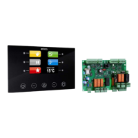
c-pro 3 OEM
K1
++ +
USB
INTRA
BUS
RS-
485
CAN
GND
Data
GND
+
-
GND
+
-
K2 K3 K4 K5 K6
Max. 12 A
2
1
ON
AO4AO3 AO2AO1 M9 M8
C1 NO1 C2 NO2 C3 NO3
M7 M6 M5 M4 M3
C4 NO4C5 NO5
M2 M1 GND 12V
NO6C6 NC6
ITB GND A+
HV1HV1 HV2 HV2
B- C+ C-
PS PS
5V
DIHV5 DIHV5
IN OUT
12
ON
Pulse - EPB90V
114CP3OEE104
c-pro 3 OEM - Hardware manual
Electrical connection
Open frame version
Analog output 4
Digital output 1
Power supply
(115... 230 VAC)
Digital input 1
Digital input 2
Digital output 4
Digital output 2
Digital output 5
Digital output 3
Digital output 6
Analog output 3
Analog output 2
Analog output 1
Digital input 4
Digital input 3
Analog input 7
Analog input 6
Analog input 5
Analog input 4
Analog input 3
Analog input 2
Analog input 1
USB
cable
PC with
UNI-
PRO 3
BMS
Device
with
INTRABUS
Device
with
CAN port
Termination of the RS-485 MODBUS and CAN networks.
Polarisation of RS-485 MODBUS network
To terminate the RS-485 MODBUS network:
– Place the micro-switch 1 in position ON
To terminate the CAN network:
– Place the micro-switch 2 in position ON
The RS-485 MODBUS network can be polarised using the
UNI-PRO 3 development environment.
Electric system
(230 VAC)
Electric system
(230 VAC)
Mains supply
(115... 230 VAC)
Neutral
Pulse
valve
Phase
Digital input 5