1143W24E4.00 · EV3 200 Web 03/2021
| 14 |
4.1.3 Permitted lengths of wiring
NOTICE
INOPERABLE DEVICE
• Whenconnectingtheprobes,thedigitalinputsandthepowersupply,usecableswithamaximumlengthof
10 m (32.80 ft).
• Whenconnectingthepowersupplyofthecontrollerandtherelayoutputs,usecableswithamaximumlengthof
10 m (32.80 ft.).
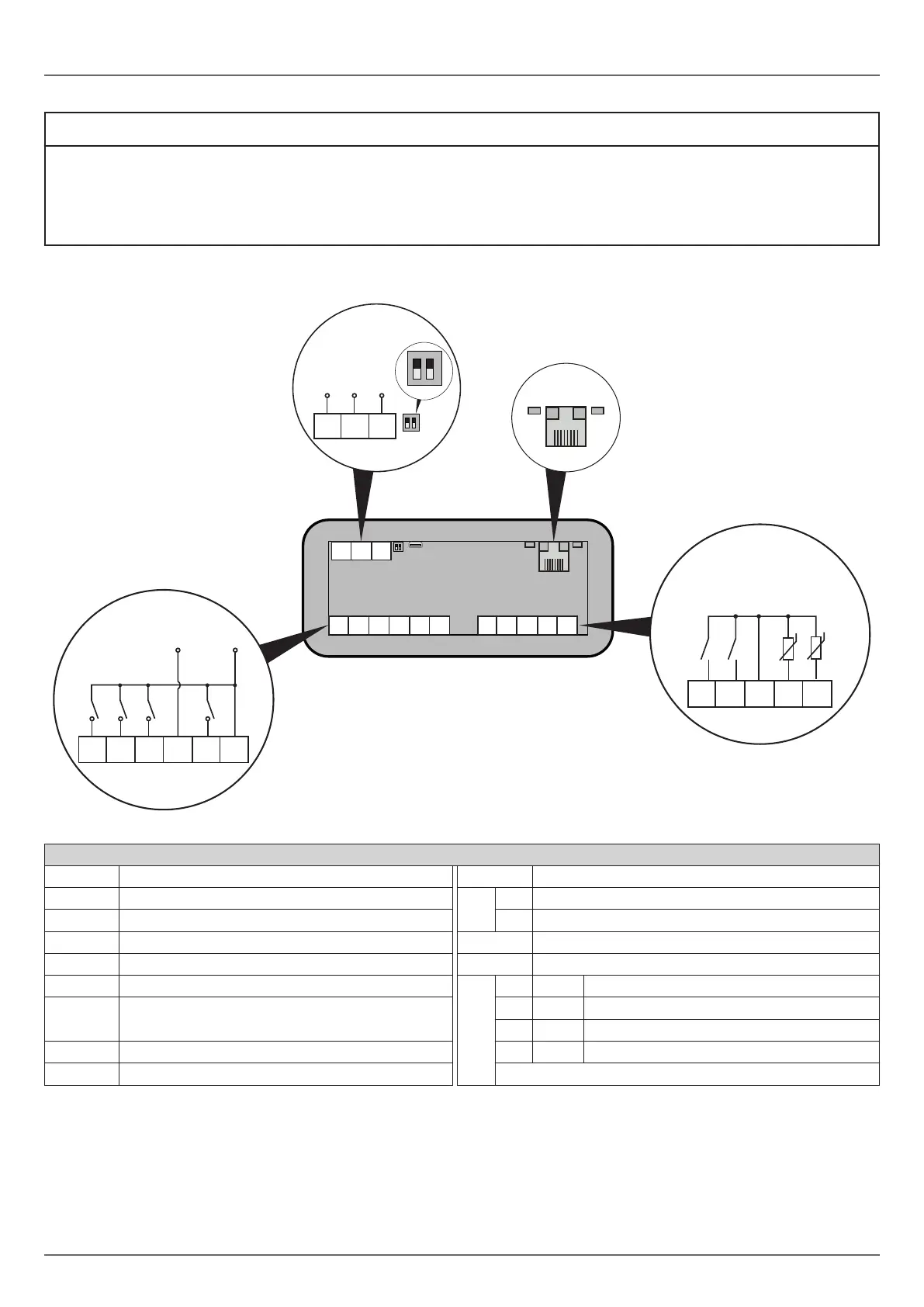
4.2 WIRING DIAGRAM
1 2 3 4 5 6
1
2
13 14 15
Out2
A+
Out4
Out3
Out1
Power Supply
Maximum 12 A
USB
LT
Pb1
Pb2
ID1
ID3
RS-485
EV3 200 Web
ON
1
2
1
2
13 14 15
RS-485
ETHERNET
ETHERNET
8 9 10 11 12
8 9 10 11 12
1 2 3 4 5 6
B- GND
LD3
LD1
LD2
LD4
ON
1
2
ON
1
2
LT
LT
Fig. 5. Wiring diagram
TERMINALS
1-6 Relay output Out1 (Compressor) 13-14-15 RS-485 serial input
2-6 Relay output Out3 (Fans)
LT
1 ON = Termination resistor inserted
3-6 Relay output Out4 (Defrost) 2 Reserved
4-6 Power supply input USB USB 2.0 input for communication
5-6 Relay output Out2 (AUX)
ETHERNET
RJ45 connector to connect to Ethernet serial port
8-10 Digital input ID1
LED
LD1 Red
Flasheswithmessagesfromsubnetwork
9-10
Digital input ID3 (if P4=0)
Probe input Pb3 (if P4≠0)
LD2 Green StaysonifconnectedtoEPoCA
LD3 Red StaysonwithEthernetlink-up
11-10 AnalogueinputPb1 (Temperature) LD4 Green Stays on with Ethernet activity
12-10 AnalogueinputPb2 (Evaporator) LEDs off: No communication