35
Component Identification and Explanation
Control Panel Operation and Navigation
NAVIGATING THE PANEL AND SCREEN: POWERSET MODE.*
Navigation in the PowerSet mode is similar to navigation in the Manual
mode. As far as the PowerSet control panel goes, the basic principle of
operation is the same for items such as program/save key, gas purge key
and up/down key as it is in the Manual mode. However, there are differ-
ences in the screen menu item lines and the way they are adjusted or set.
The user input data set also differs from the Manual mode. For the sake of
continuity and to highlight similarities and differences between the opera-
tion of Manual and PowerSet modes, all panel controls, functions and
features already discussed in manual mode are also discussed again in
context of the PowerSet mode in the information below.
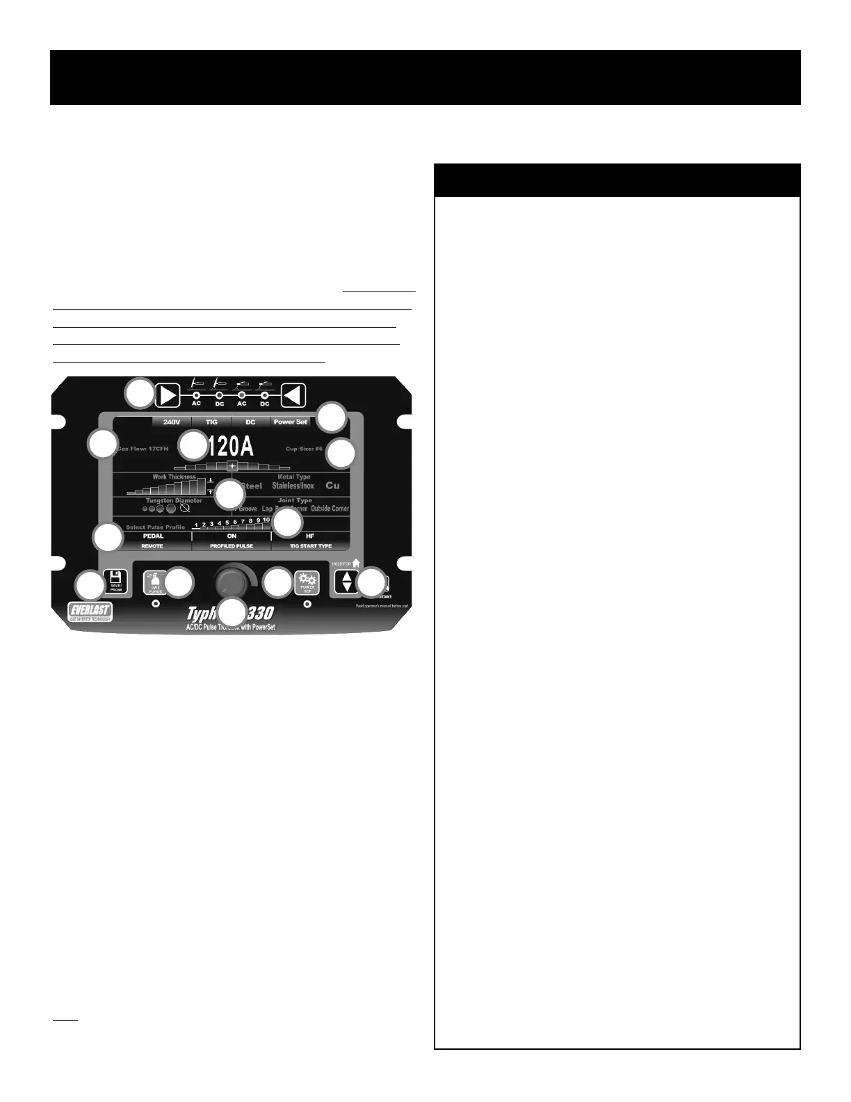
See the information below list for a basic understanding of the functions
and features of the control panel and screen:
1. Function Selector. The left and right keys allow the user to move left
or right to select between AC TIG, DC TIG, AC Stick, and DC Stick.
As the keys are pressed the LED will move to the next function. When
the function has been selected, the appropriate screen will be dis-
played and will be ready for further adjustment and navigation.
2. Save/Program Key. The Save/Program key pulls up the program
screen when pressed. When pressed in simultaneously and held
along with the Gas Purge key (#3), the hidden parameter menu will
be brought up.
3. Gas Purge Key. When pressed, the LED light will illuminate and the
gas solenoid valve will open to allow the user to set the gas flow rate
without having to trigger the torch. To stop constant gas flow, press
again and the LED will turn off and the gas flow will cease. When
pressed in simultaneously and held along with the Save/Program Key
(2#), the hidden parameter menu will be brought up.
4. Adjustment Knob. In PowerSet mode, the function of this knob only
allows adjustment or change in an input or function. Adjust input
1
2
3
4
5 6
7
8
9
10
11
12
9a
What is the PowerSet Mode?
The PowerSet menu screen simplies setup by providing a starting point
Amperage and by presetting many adjustable settings such as Pre-Flow,
Post Flow, AC Frequency, AC balance, and pulse parameters. The pur-
pose of the PowerSet menu screen is to reduce operator effort and setup
time for new hires, and professional users that need to bypass the more
extensive manual setup routine. The PowerSet Mode can be useful to
beginners, but it is intended for professional users because it still re-
quires a solid knowledge base and skills to make it work properly.
The PowerSet is able to make Amperage recommendations by request-
ing the user to enter known or determinable data relating to the weld
such as thickness of the part to be welded (work thickness), the diameter
of the tungsten being used, the metal type and the joint type. Once those
inputs are complete, the unit provides the user with a useable starting
point Amperage. It also suggests other standard information such as
cup size and gas flow rate.
This is only a suggested starting point. The Amperage may then be ad-
justed up or down from that point, within limits. The adjustment limits
are designed to allow ne tuning without allowing the user to stray too
far off of good known settings. The adjustments will allow a basic range
of 20 Amps total deviation from the recommended setting. This means
the programming will allow the user to increase or decrease Amps a
total of 10 Amps from the suggested setting.
As you get further away from a recommended setting, the stepped
graphics under the Amperage will turn red to warn that the adjustment
may be getting too far away from a desirable setting. However, it will not
prevent the user from making further adjustment until the range limit has
been reached. Each step represents 2 Amps of adjustment value.
Almost all function settings have been xed at an optimum setting for
general purpose use. The Proled Pulse has 10 preset programs which
allow the user to use the pulse without trial and error.
The PowerSet mode has limitations. It cannot predict all possible work
conditions. If PowerSet mode does not yield satisfactory results, then
use the Manual mode for full adjustment ranges and functions. It is not
intended for all types of metals. Titanium is not included in this menu.
PowerSet Preset Values (For DC, omit AC References):
Pre Flow: .5 Seconds
Post Flow: 3 Seconds
Start Amps: 20A
End Amps: 20A
AC Frequency: 120Hz
AC Balance: 27% of EP+
AC Wave Form: Balanced EP+ and EN-, Adv. Square Wave
AC Independent Amplitude: Balanced Amp Setting.
Proled Pulse Amp Setting: 35%
Proled Pulse Time On: 50%
Proled Pulse Frequency (Hz): #1=.5Hz, #2=1Hz, #3=10Hz, #4=50Hz,
# 5=100Hz, #6=150Hz, #7=200Hz, #8=300Hz, #9=400Hz, #10=500Hz
 Loading...