Mechanical Installation
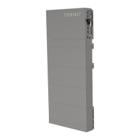
b) Mark the hole location and drill holes;
Ÿ Place the assembled transverse plate and base support on the wall, look the
cylindrical plastic bubble spirit level on the transverse plate. If the bubble
isn't in the center, slightly bow it to the horizontal.
Ÿ Then determine the position of holes.
Ÿ Mark it with a marker.
Ÿ
Note: The distance from the Base to
the ground is decided according to
the local regulations.
Ground
3
2 i
n
/8
12
.8
mm
Cylindrical plastic
bubble spirit level
NOTE!
The bubble spirit level on the transverse plate can be used as an
auxiliary tool. Additionally, please prepare a spirit level to measure
whether the plate is even or not.
60
Mechanical Installation
61
Remove it and drill the four holes (at least 3.54 in./90 mm) by Drill (Ø 0.47 in./12
mm for concrete wall, or Ø 0.24 in./6 mm solid wood wall)
(2) Solid Wood Wall
≥1.97 in./
50 mm
Ø 0.24 in./6 mm
for Base Support
(1) Concrete Wall
Ø 0.47 in./12 mm
for Base Support
≥3.54 in./
90 mm
90° 90°
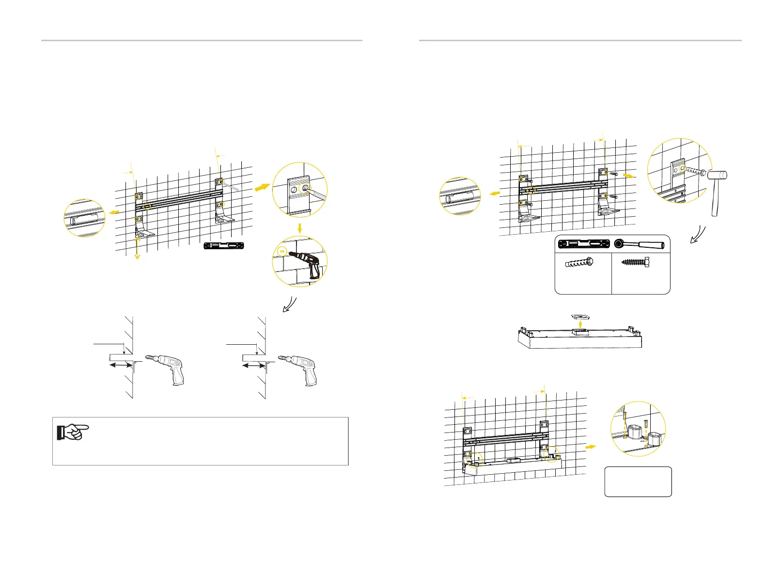
c) Secure the assembled transverse plate on the wall;
(1) Place the assembled Transverse Plate and Base Support to the wall (or solid
wood wall);
(2) Attach screws to the holes
e) The steps of mounting battery modules, BMS and inverter are same as
the floor-mounting's. Please refer to “7.3 Floor-mounting” for more details.
• In the case of the concrete wall, attach the M8*85 Expansion Screw (× 4) to the
holes but be sure not to tighten (Torque: 10 N·m);
• Or, in the case of solid wood wall, attach M8*89 Self-tapping Screw (x 4) to the
holes but be sure not to tighten (Torque: 10 N·m);
(3) Check whether the cylindrical plastic bubble spirit level is horizontal;
(4) Hammer Expansion Screws with a rubber mallet (expect solid wood wall), and
tighten it with torque wrench.
Cylindrical plastic
bubble spirit level
Ø 0.47 in./12 mm
For concrete wall
10 N·m
x 4 x 4
Ø 0.24 in./6 mm
For solid wood wall
10 N·m
32 in./812.80 mm
d) Place the base.
(1) Remove the dust cover.
(2) Place Base on the Base Support and secure both left and right sides with screws
(4 × M5*20 countersunk screw) (Tighten torque: 2.2-2.5 N·m).
M5*20 Screw × 4
2.2 - 2.5 N·m
32 in./812.80 mm