Wiring Connection on the Inverter
Wiring Connection on the Inverter
74
For the specific requirement of cable, please refer to “Appendix A: Wiring
and Breaker Requirement”.
.
8.4 Communication Connection
All communication cables will be done on the communication board which is
in the wiring box.
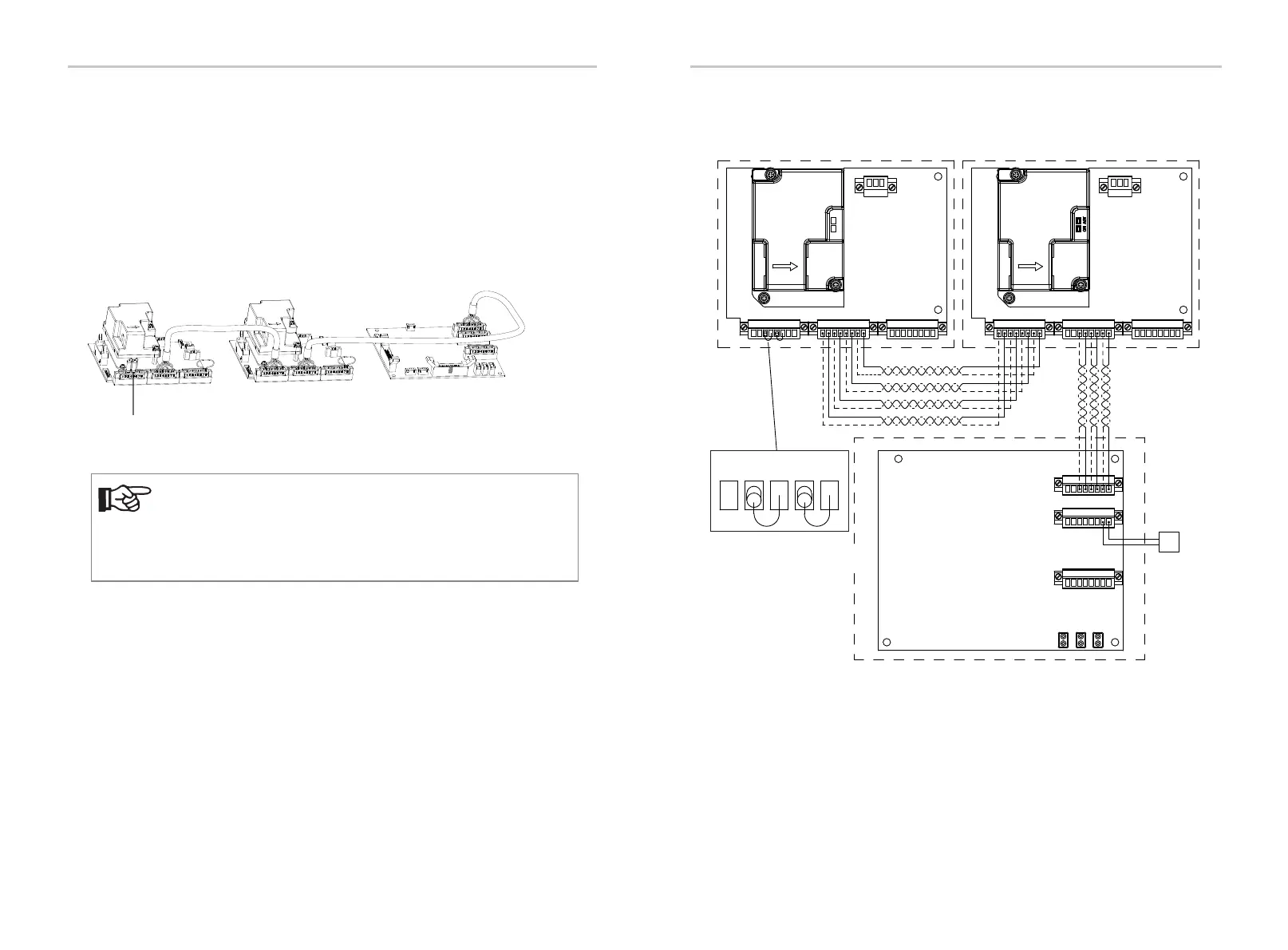
8.4.1 Make Communication Connection to Another Inverter/EV-SB
Ÿ Inverter communication system diagram
NOTE!
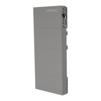
In the first inverter of the communication chain, plug the 8-pin female
block with the terminating 120-Ohm resistor into the 8-pin male block.
Maximum four inverters can be communicated via communication
cable.
120-Ohm terminating resistor
Inverter
Inverter
AUX1
AUX AUX
COMM OUT COMM OUT
COMM IN COMM IN
AUX2
CT1 CT2 CT3
EPO
INV
ON
ACT
1 2 3 4 5 6
7
8
1 2 3 4 5 6
7
8
1 2 3 4 5 6
7
8
1 2 3 4 5 6
7
8
1 2 3 4 5 6
7
8
1 2 3 4 5 6
7
8
1 2 3 4 5 6
7
8
2 3 4 5 6
1 2 3 4 5 6
7
8
1 2 3 4 5 6
7
8
Ÿ Detailed communication connection diagram
Inverter Inverter
EV-SB
EV-SB
MLPE
3 2 1
MLPE
3 2 1
75