Wiring Connection on the Inverter
Wiring Connection on the Inverter
64
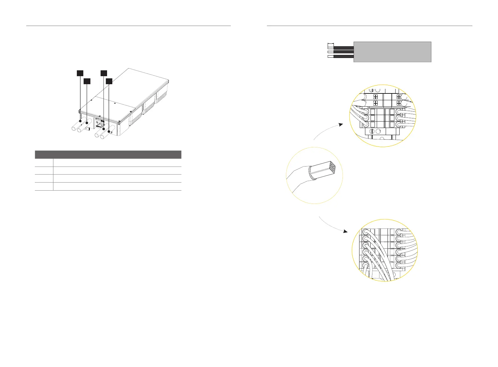
Ÿ General steps of connecting electrical wirings to terminals
Step 1: Choose the appropriate wire according to the specific connection.
8.2 Power Connection
Strip Length
Conduit
0.47 in / 12 mm
Wirings
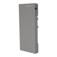
Ÿ Cable entry of inverter
AC wire connection
DC wire connection
Step 2: Remove 0.47 in / 12 mm of insulation from the end of DC wire and the AC
wire.
Step 3: Insert the end of wires into the Cord End Terminal, and then use the
crimping tool to crimp the Cord End Terminal tightly (the shape will be square).
Step 4: Use the slot screwdriver to compress the orange button of the terminals.
Then insert stripped wires into the terminal and ensure that all conductor strands
are captured in the terminal.
Step 5: Loosen the slot screwdriver.
For the specific requirement of power cable, please refer to “Appendix A: Wiring
and Breaker Requirement”.
A conduit fitting or cable gland must be used when wiring connection. The cable is
routed from the right side of inverter.
A
B
C
D
A
B
C
Item Type of Cable Entry
Conduit plug for AC connection
Conduit plug for communication connection
Conduit plugs for PV connection
D
Conduit plugs for PV connection
65