EPO
1
8
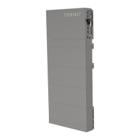
Step 1: Remove the factory-installed jumper from Pin 7 and 8 of the 8-
position “AUX” connector inside the inverter.
Step 2: Use minimum 24 AWG conductors to connect Pin 7 and Pin 8
(labeled “12V” and “STOP_NO”) to a suitable emergency stop switch.
For installing EPO on the inverter, follow the below installation instructions.
Appendix B EPO Connection Steps
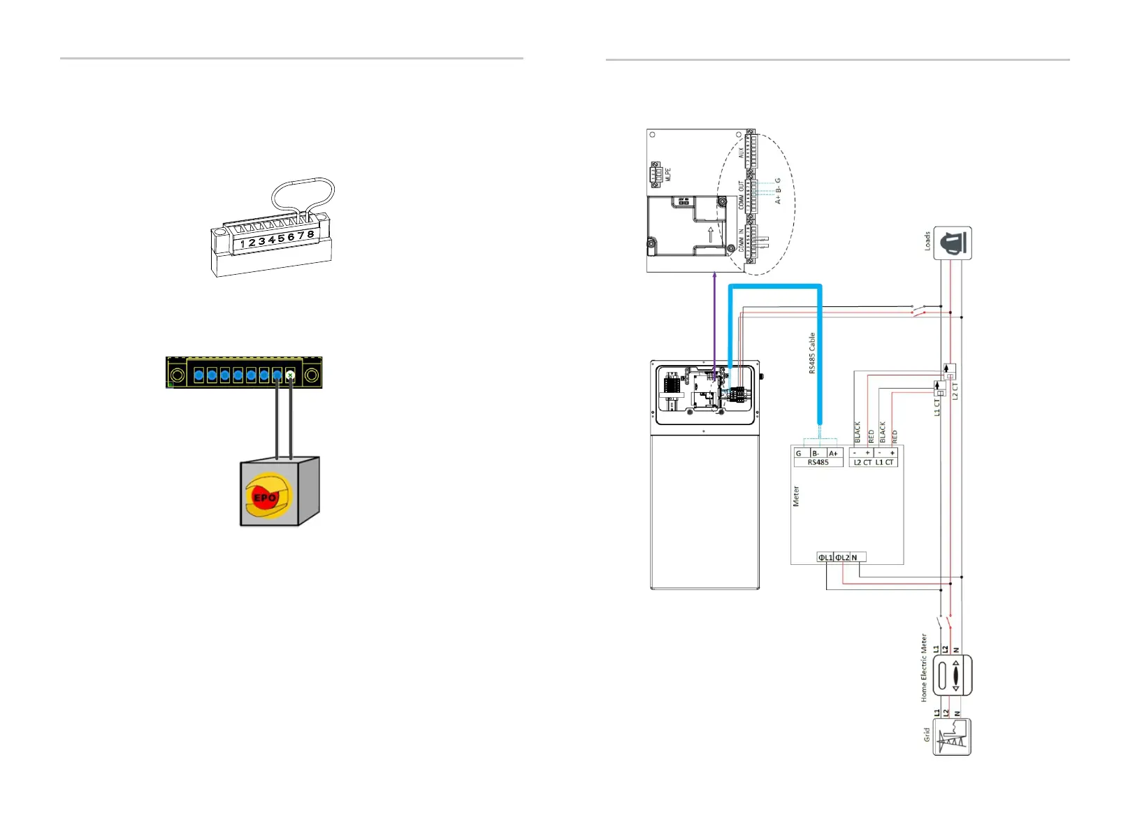
Appendix C Meter Y Connection Diagram
Appendix B: EPO Connection Steps
Appendix C: Meter Y Connection Diagram
128
129