Wiring Connection on the Inverter
Wiring Connection on the Inverter
76
Communication connection between inverter and EV-SB:
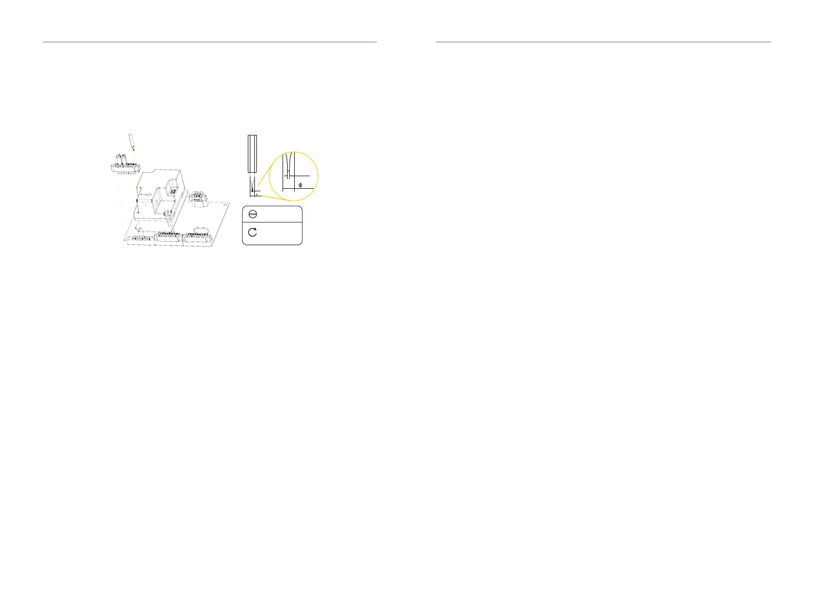
Step 3: Plug stripped wires into female terminal and ensure that all conductor
strands are captured in the terminal.
Step 4: Screw down screw cap tightly.
Step 5:
Connection between inverters:
Connection between inverter and EV-SB:
Pin 3-Pin 6: Select the CAT5 or better (24-18 AWG), use diagonal plier to cut off
four wires and leave four wires for connection. Remove 0.24 in / 6 mm of insulation
from the end of the four wires.
Pin 7-Pin8: Select two 18-16AWG wires and remove 0.24 in / 6 mm of
insulation from the end of the two wires.
Plug the female terminal block into the COMM OUT male terminal block on the
communication board of the first inverter and screw in each screw tightly. And plug
another end of female terminal block into the COMM IN male terminal block on the
communication board of the second inverter.
Plug the female terminal block into the COMM OUT male terminal block on the
communication board of the inverter and screw in each screw tightly. And plug
another end of female terminal block into the INV communication terminal of EV-SB.
For the specific communication terminal on the EV-SB, please refer to “Chapter 9
Wiring Connection on the EV-SB”.
Ÿ Connection steps of terminating resistor
Step 1: The 120-Ohm resistor has been pre-installed on the 8-pin female
block before leaving factory. Take it out from the accessory box.
Step 2: Install the 8-pin female block with resistor to the COMM in male
terminal by using slot screwdriver.
Ÿ Connection steps of communication wire
Step 1: EVHB series inverter supports to be connected with additional
three inverters in maximum. Disassemble 8-pin female blocks prior to
communication connection.
Step 2:
Communication connection between inverters:
Pin 1-Pin 6: Select the CAT5 or better (24-18 AWG), use diagonal plier to cut off
two wires and leave six wires for connection. Remove 0.24 in / 6 mm of insulation
from the end of the six wires.
Pin 7-Pin8: Select two 18-16 AWG wires and remove 0.24 in / 6 mm of
insulation from the end of the two wires.
1.8 lbf.in /
0.2N·m
0.5
2.5
0.5
2.5
77