Ÿ Communication connection between inverter and EV-SB
Please refer to Section 8.4.1 Make communication connection to another
inverter/EV-SB forthedetailed steps of connection.
EPO
1
8
94
Install generator
Step 1: Use the same 8-Pin female terminal of EPO,
Step 2: Use minimum 24 AWG conductors (maximum 16 AWG) for
generator to connect Pin 1 and Pin 2 (Pin 7 and Pin 8 for EPO). The rest pins
are reserved.
Step 3: Remove 0.24 in / 6 mm of insulation from the end of the four wires.
Step 4: Insert the stripped wires into female terminal and ensure that all
conductor strands are captured in the terminal. and plug the female terminal to
AUX1 port.
Ÿ Communication connection of EPO and generator
The EV-SB can be wired to include an external emergency stop button that can
switch off the whole system.
The EPO and generator share the same AUX1 port.
3 Confirm the system will cease operation when the switch is open.
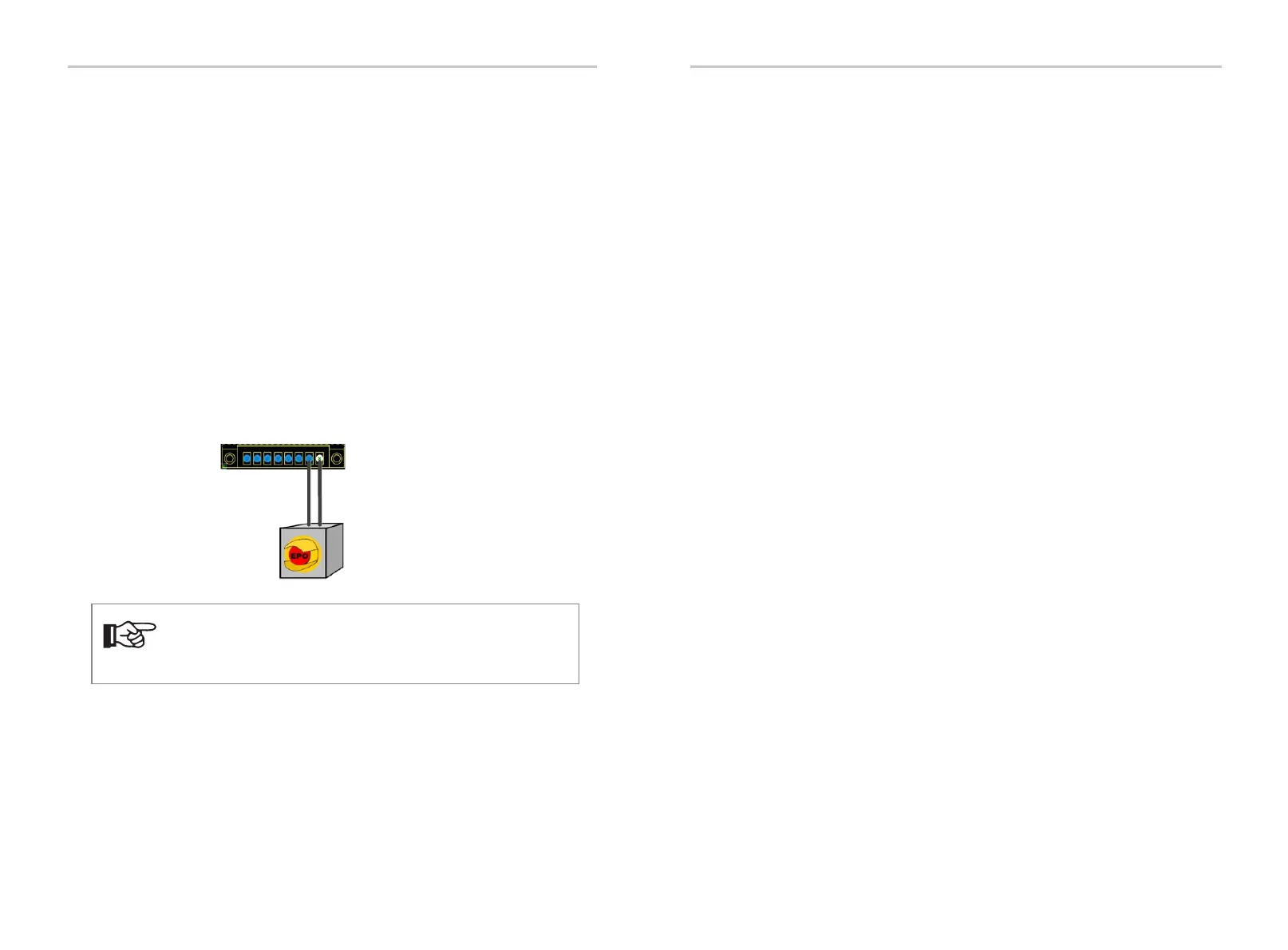
Install optional EPO
1 Remove the factory-installed jumper from Pin 7 and Pin 8 of the 8-position
“AUX1" connector inside the EV-SB.
2 Use minimum 24 AWG conductors (maximum 18 AWG) for EPO to connect
Pin 7 and Pin 8.
NOTE!
Turn the switch to OFF (open) position: The whole system will go
to idle; turn the switch to ON (closed) position: The whole system
will resume shortly.
95
Wiring Connection on the EV-SB
Wiring Connection on the EV-SB