110
ENGINE MANAGEMENT MODULE (EMM)
EMM SERVICING
EMM SERVICING
IMPORTANT: If a new EMM is being installed,
refer to EMM Transfer on p. 109.
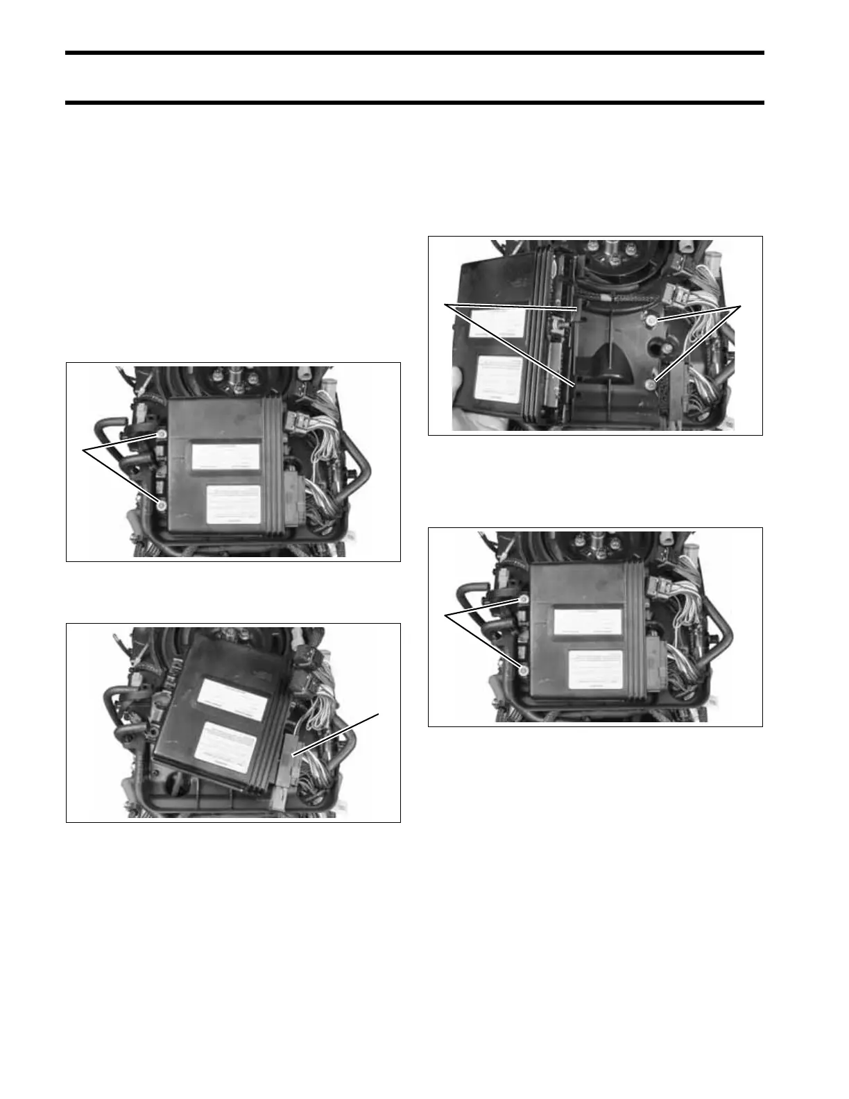
Removal
Disconnect exhaust pressure hose and cooling
hoses from EMM.
Disconnect J1-A and J1-B connectors.
Remove two EMM retaining screws. Lift EMM up
and to the port side.
Disconnect J2 connector.
Installation
Install J2 connector
Align slots in starboard side of EMM case with iso-
lator mounts on electrical harness base. Slide
EMM into position.
Install two EMM retaining screws. Tighten screws
12 to 16 in. lbs. (1.5 to 2 N·m).
Install J1-A and J1-B connectors.
Install exhaust pressure hose and cooling hoses.
Secure with tie straps.
1. EMM mounting screws 005375
1. J2 Connector 005376
1
1
1. EMM mounting slots
2. Isolator mounts
005377
1. EMM mounting screws 005375
21
1