155
ELECTRICAL AND IGNITION
TIMING ADJUSTMENTS
7
Rotate the flywheel clockwise until the piston
contacts the tool. Mark the flywheel directly across
from the pointer. Label this mark “B.” Rotate fly-
wheel counterclockwise slightly to release tool
then remove it from spark plug hole.
Use the cast in markers on the flywheel to calcu-
late the exact center between marks “A” and “B.”
Mark and label the center point “C.”
If mark “C” and the cast-in TDC boss on flywheel
are in alignment, the timing pointer is in the cor-
rect location.
If the pointer alignment is NOT correct, rotate the
flywheel clockwise to align the mark “C” with the
pointer. Hold the flywheel in this position. Loosen
the pointer retaining screw and adjust the pointer
location to align with the cast-in TDC boss on the
flywheel. Tighten retaining screw.
Repeat the entire adjustment process to make
sure pointer is aligned correctly.
Install spark plugs. Refer to Spark Plug Indexing
on p. 84.
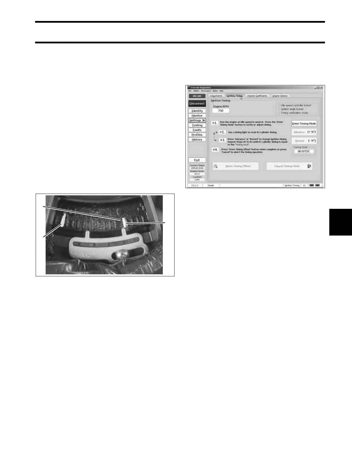
Timing Verification
Use Evinrude Diagnostics software to synchronize
the mechanical timing of the outboard with the
electronic timing of the EMM.
Check ignition timing after any of the following
procedures:
• Powerhead replacement
• Crankshaft replacement
• Flywheel removal or replacement
• CPS replacement
• EMM replacement
• EMM software replacement (reprogramming)
IMPORTANT: Make sure the timing pointer is
set and the outboard reaches operating tempera-
ture before timing verification is performed.
1. Cast in TDC mark
2. Mark B
3. Mark C
005388
3
1
2
Timing Adjustment Screen 006547