121
SYSTEM ANALYSIS
IGNITION OUTPUT TESTS
6
Ignition Primary Circuit
Resistance Test
Disconnect the battery cables at the battery.
Calibrate ohmmeter to low ohms scale.
With key switch OFF, remove the EMM J1-B con-
nector and measure resistance of each primary
circuit. Note resistance reading between each pri-
mary wire and ground. Refer to engine wiring dia-
gram.
IMPORTANT: A reading of less than 2 ohms is
acceptable. Make sure meter is calibrated to read
1 ohm or less.
Results:
Primary circuit (complete circuit) resistance read-
ing is higher than 2 Ω:
• Repair primary circuit wiring or coil grounds as
needed and retest.
• Replace faulty coils or wiring.
Primary circuit resistance reading less than 2 Ω or
within specification and EMM ignition output volt-
age is 130 V or higher:
• Refer to Ignition Coil Tests on p. 121. Repair
high tension spark plug lead or replace ignition
coil and/or high tension spark plug lead assem-
bly.
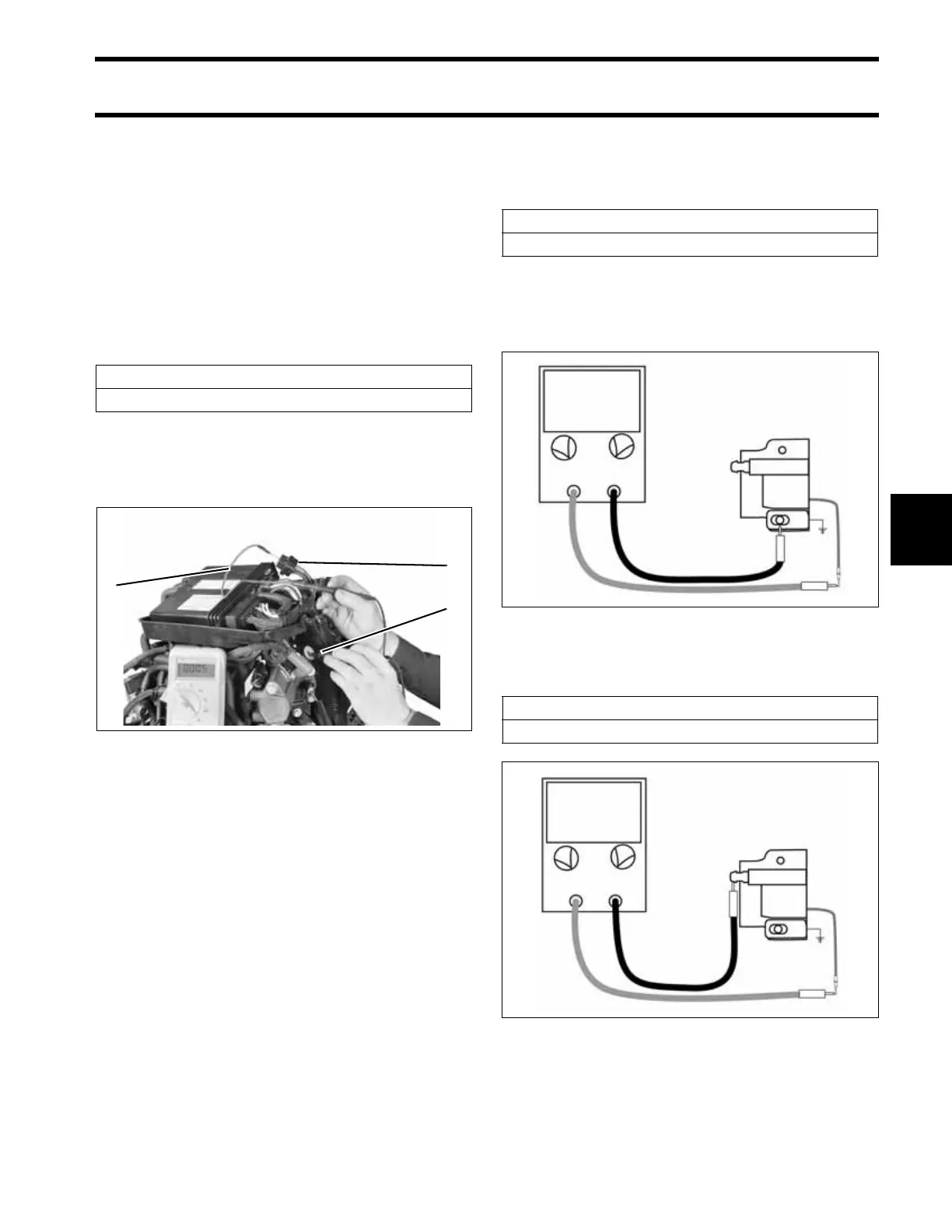
Ignition Coil Tests
Connect a digital multimeter between coil primary
terminal and clean engine ground.
IMPORTANT: A reading of less than 2 ohms is
acceptable. Make sure meter is calibrated to read
1 ohm or less.
Connect meter between coil secondary terminal
and coil primary terminal.
Ignition Coil Primary Circuit Resistance
0.090 ± 0.005 Ω.
1. J1-B connector
2. Red meter lead, with pin adapter
3. Black meter lead to ground
005440
1
3
2
1
Ignition Coil Primary Resistance
0.090 ± .005 Ω @ 77°F (25°C)
000741
Ignition Coil Secondary Resistance
301 ± 14 Ω @ 77°F (25°C)
000742