141
ELECTRICAL AND IGNITION
ELECTRIC START TESTS
7
Key Switch, START Position
Key switch START:
• Switches 12 V to terminal “S” of key switch and
to the neutral safety switch (in remote control).
• A closed neutral safety switch provides 12 V to
the engine wire harness yellow/red wire and
terminal 26 of EMM J-1A connector.
• EMM grounds brown/white wire to activate sole-
noid.
ELECTRIC START TESTS
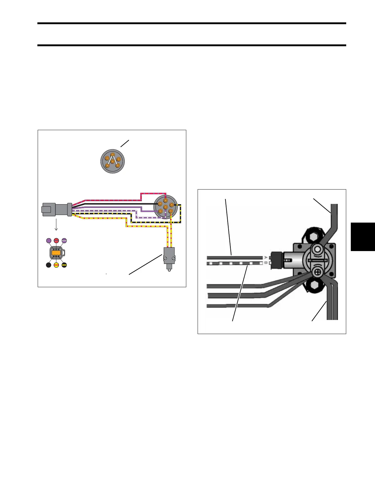
Starter Solenoid Test
Disconnect the B+ (POS) battery cable at the bat-
tery.
IMPORTANT: Disconnect all wiring from sole-
noid terminals before proceeding with this test.
Use a digital multimeter to measure resistance.
Put one meter lead on the starter positive (+)
cable terminal and the other lead on the battery
positive (+) cable terminal:
• Meter must not show continuity (high reading).
• If meter shows continuity (low reading), replace
the solenoid.
Apply B+ to terminal “A” of solenoid and ground
(NEG) to terminal “B” of solenoid. Measure resis-
tance between the starter positive (+) cable termi-
nal and the positive battery (+) cable terminal.
• The solenoid must close with an audible click.
• Meter must show continuity (low reading).
• If meter shows no continuity (high reading),
replace the solenoid.
1. Ignition switch, START position – Continuity
between terminals “B” and “A”; “B” and “S”
2. Terminal “S”, 12 V
3. Neutral safety switch
000691R
1
2 3
B
M
M
C
A
S
M
B
S
A
C
M
456
123
1. “A” terminal, B+ (purple)
2. “B” terminal, NEG (brown/white)
3. Starter positive (+) cable terminal
4. Battery positive cable (B+) terminal
004121
13
2 4