Chapter 3
Base Unit Hardware Description
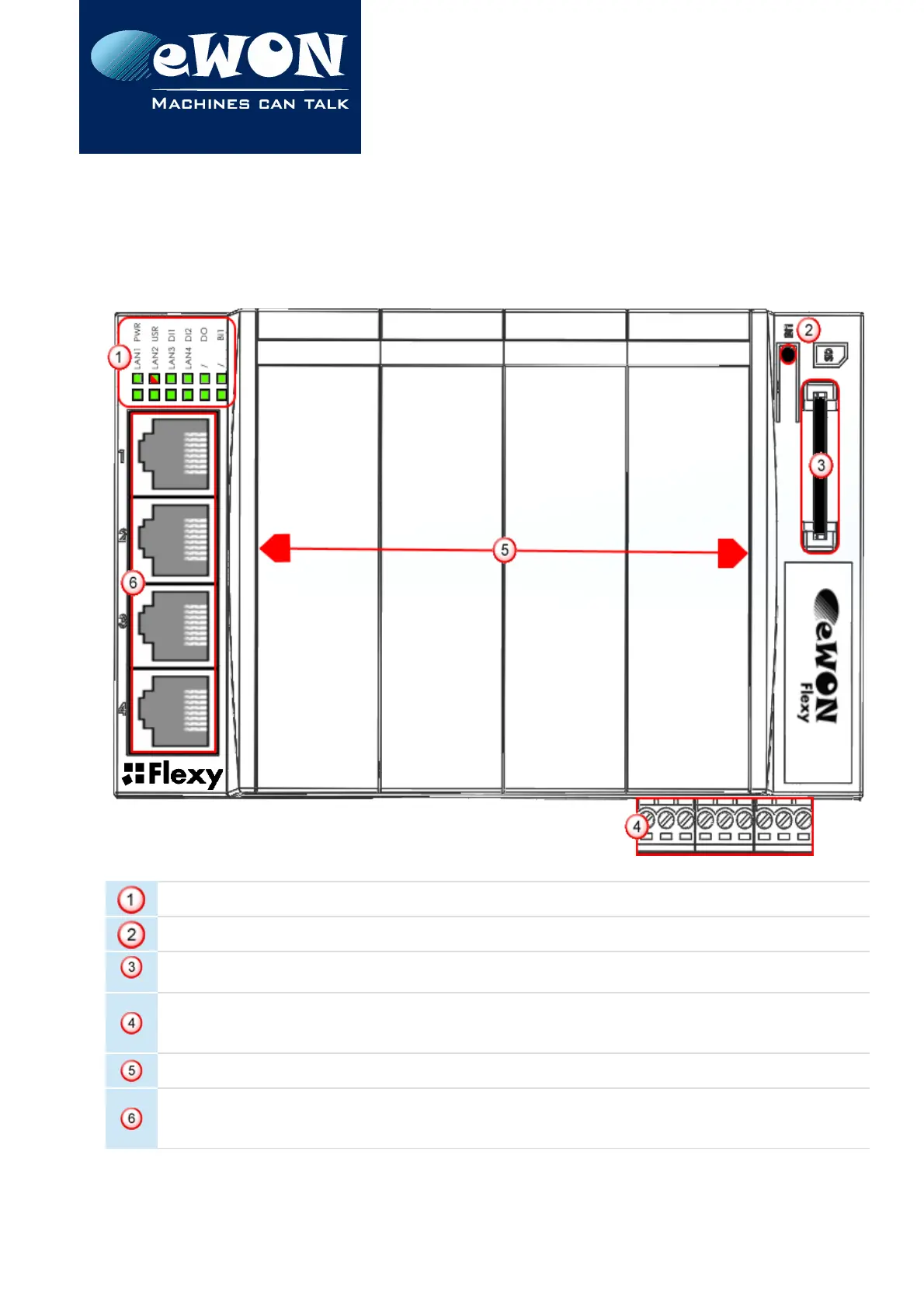
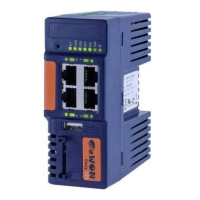
3.3. Base Unit Interface
This chapter addresses the interface that represents the Base Unit. The items numbered in
the image below are explained subsequently in separate paragraphs.
LED panel
RESET button (BI1)
SD card slot
Main connector
used to connect the power supply and the digital inputs & outputs
4 slots fillers (that can be removed and replaced by Extension Cards)
Main board communication interfaces (depending on the Base Unit type)
(In our example: 4 Ethernet Ports)
Page 17 / 40 eWON Flexy - Base Units | IG 014