Appendix A - Connector Pinout & Related
Specifications
Appendix A - Connector Pinout & Related Specifications
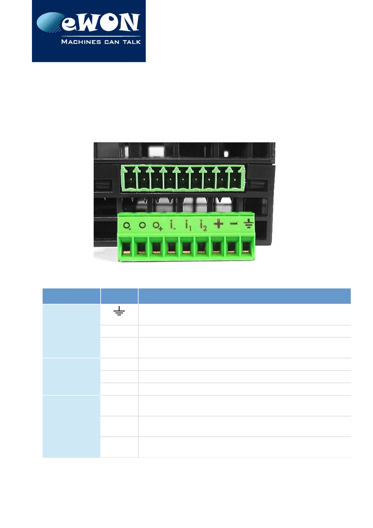
A.1 - Main Connector
As shown on the picture, the female mating connector is labeled with the appropriate
symbols.
From right to left
Item Labels Description
Power
Supply
Functional Earth (FE)
See § 2.6 Field Implementation & Environmental Conditions
-
Power in GND - (0V)
+
Power in VDD + (between +12 et +24 VDC)
Related specification see below
Digital Inputs
i
2
Input signal 2 - Related specification see below
i
1
Input signal 1
i
-
Common ground of the inputs (isolated)
Digital Output
O
+
Common of the external predrive power supply
(between +12 and +24 VDC)
O
Output signal
connected to the drain of the MOSFET transistor
O
-
Output signal (0V ground)
connected to the emitter of the MOSFET transistor
Page 34 / 40
eWON Flexy - Base Units | IG 014