Maintenance
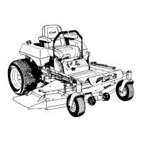
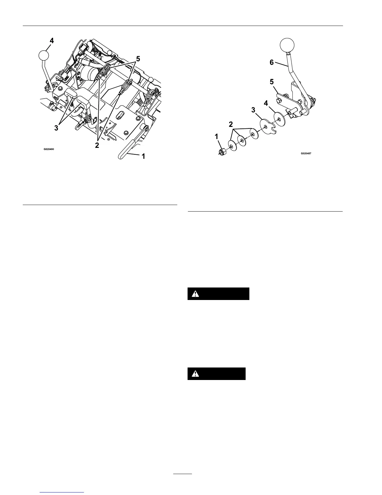
Figure32
1.Parkingbrake
4.Speedcontrollever
2.Nut
5.Clevispinandstoprod
3.Steeringlever
E.Engagetheparkingbrakeandcheckthe
steeringlevers.
RepeatstepsCthroughEuntilupto1/8
inch(3mm)movementisachieved.
F.Reinstalltheseatframeassembly,if
removedinstepA.
AdjustSpeedControlLever
Tension
1.Stopengine,waitforallmovingpartstostop,and
removekey.Engageparkingbrake.
2.Tensioninspeedcontrollevercanbeadjusted
byadjustingthetightnessoftheleverpivotnut
whichislocatedattheendofthemotioncontrol
shaftinfrontoftheRHconsole(seeFigure33).
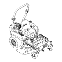
Figure33
1.Nut4.Frictiondisc
2.Springdiscwashers5.Speedcontrolfriction
bracket
3.Speedcontrolfriction
plate
6.Speedcontrollever
3.Setthetensionhighenoughthatthespeedcontrol
leverpositionismaintainedduringoperationand
looseenoughtobemovedcomfortablybythe
operator.
SpeedControlLinkage
Adjustment
WARNING
Enginemustberunninganddrivewheelsmust
beturningsomotioncontroladjustmentcanbe
performed.Contactwithmovingpartsorhot
surfacesmaycausepersonalinjury.
Keepngers,hands,andclothingclearof
rotatingcomponentsandhotsurfaces.
CAUTION
Raisingthemowerdeckforserviceor
maintenancerelyingsolelyonmechanical
orhydraulicjackscouldbedangerous.The
mechanicalorhydraulicjacksmaynotbeenough
supportormaymalfunctionallowingtheunitto
fall,whichcouldcauseinjury.
DoNotrelysolelyonmechanicalorhydraulic
jacksforsupport.Useadequatejackstandsor
equivalentsupport.
44
 Loading...