FOX3 T 201 Transmitter • Installation and Operation 15
RS-232 Insertion
A user can connect a control system to send and receive RS-232 data over the fiber and
the captive screw port of the transmitter and receiver.
Captive Screw Insertion
A user can connect an RS-232 signal from a control system to an endpoint and pass that
signal over the fiber to the connected endpoint. An RS-232 signal must be inserted in the
RS-232 port on the transmitter or receiver and bidirectional fiber must be used.
The RS-232 signal settings are:
• Baud rate: 9600 (default) to 115200 • Stop bits: 1 (default) to 2
• Data bits: 5 to 8 (default) • Parity: Odd, Even, or None (default)
The RS-232 insertion method must be set to Captive Screw Insertion via PCS (see the
FOX3 SR 201 Help File) on both endpoints passing the control signal.
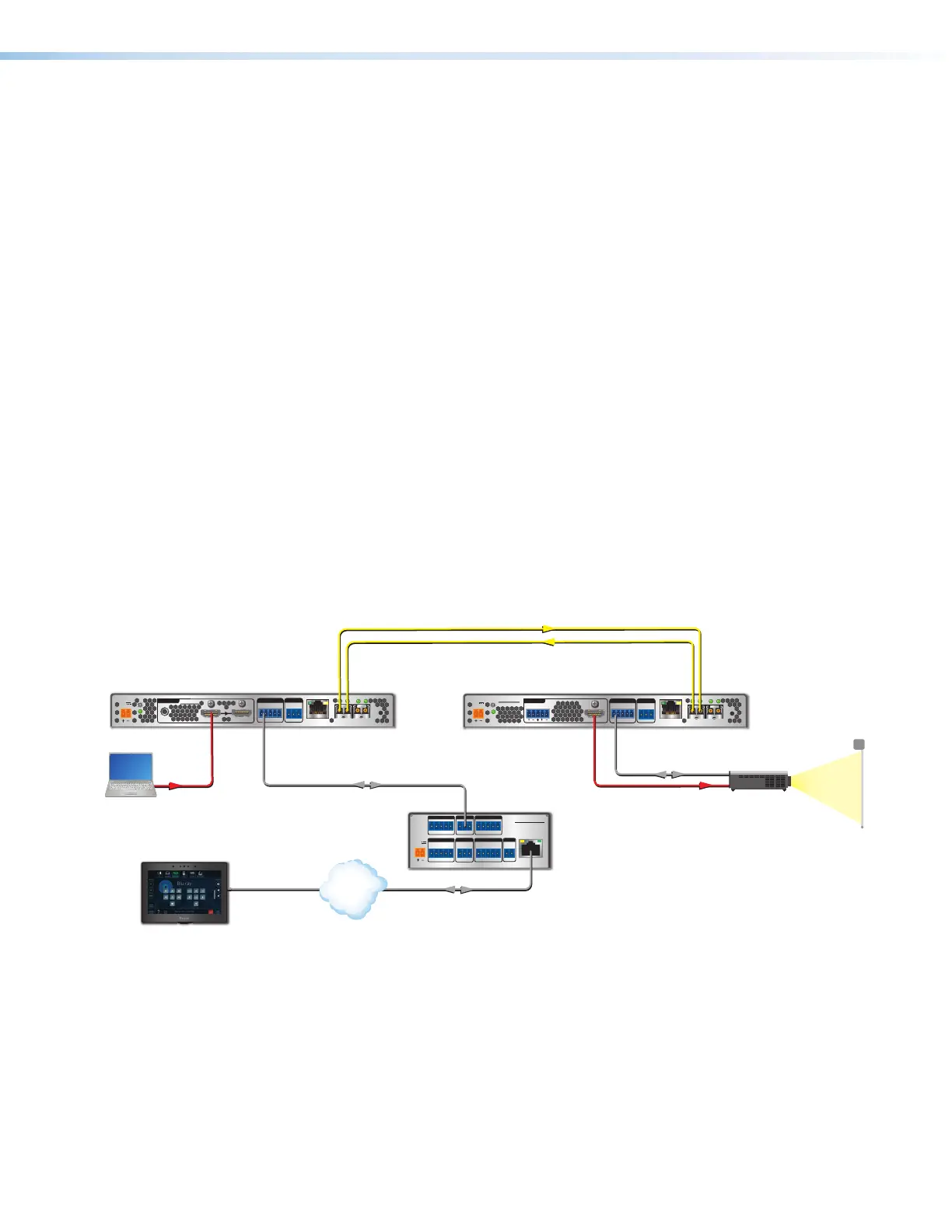
Example of a bidirectional fiber system (see figure11):
• On the FOX3 transmitter and receiver, configure the RS-232 Insertion via PCS.
• The control system then sends a control command:
• Into the transmitter Control RS-232 port.
• Out of the transmitter SFP A port to the receiver SFP A IN port.
• To the receiver captive screw port.
• Into the display to take some action.
• The response from the display is sent back to the control system.
RS-232
REMOTE
POWER
12V
0.7 A MAX
Tx Rx G
A
OUTIN
B
OUTIN
LAN
RS-232
Tx Rx Tx RxG
IR
HDMI
FOX3 SR 201
R
AUDIO
CONTROL
OUTPUTS
RS-232
REMOTE
POWER
12V
--A MAX
Tx Rx G
A
OUTIN
B
OUTIN
RS-232
Tx Rx Tx RxG
IR
HDMI
FOX3 T 201
R
AUDIO
CONTROL
INTPUTS
LOOP OUT
LAN
POWER
12V
--A MAX
G
Tx Rx RTS CTS
COM 1
G
Tx Rx
COM 2
VCG
VOL
RELAYS
1 2 C
1 2 3 4 G
DIGITAL I/O
PWR OUT = 6W
eBUS
+V +S
-S
G
LAN
IPCP PRO 250
IR/S
S G
Extron
IPCP Pro 250
IP Link Pro
Control Processor
Projector
HDMI
HDMI
ptop
Ethernet/PoE Ethernet
TCP/IP
Network
Extron
TLP Pro 725T
7" TableTop
TouchLink Pro
RS-232
RS-232
Extron
FOX3 T 201
Fiber Optic Transmitters
Extron
FOX3 SR 201
Fiber Optic Receiver
Figure 11. Typical Captive Screw Insertion Configuration
11