FOX3 T 201 Transmitter • SIS Configuration and Control 20
Using the Command and Response Table
The command and response table begins below. Symbols are used throughout the table
to represent variables in the command and response fields. Command and response
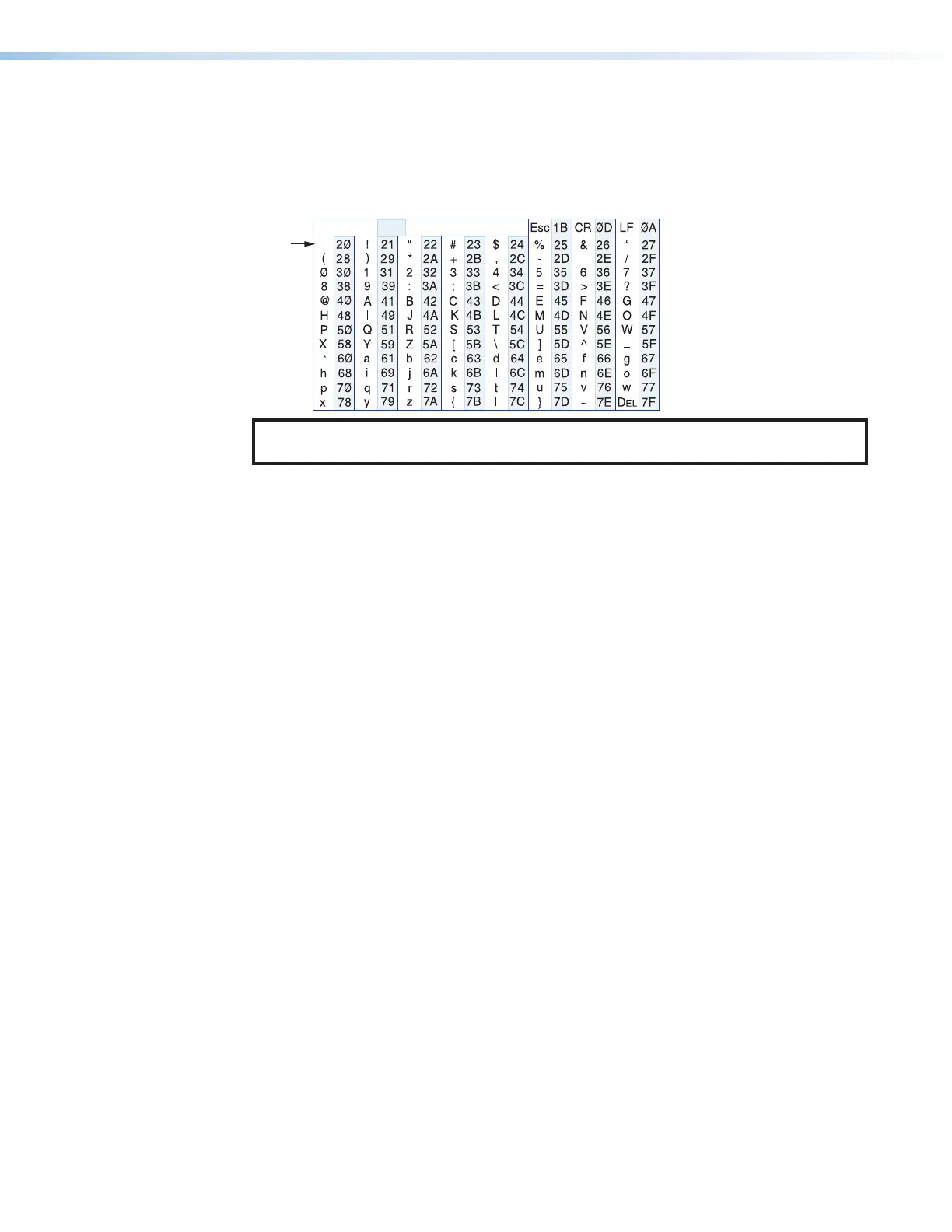
examples are shown throughout the table. The ASCII to HEX conversion table below is for
use with the command and response table.
ASCII to Hex Conversion Table
•
NOTE: For commands and examples of computer or device responses used in this
guide, the character “0” is the number zero and “O” is the capital letter “o.”
Common symbol definitions
] = Carriage return/line feed
• = Space
} or | = Carriage return (no line feed)
E or W = Escape key
X!
= Video mute 0 = Unmute (default) 1 = Mute video only
2 = Mute video and sync
X@
= Audio output 1 = Digital (Tx Loop Out)
2 = Analog
3 = All outputs (digital and analog)
X#
= Audio mute status 0 = Unmute (default), 1 = Mute
X$
= Input video signal status 0 = Not detected, 1 = Detected
X%
= Input audio status 0 = Not detected, 1 = Detected
X^
= Input HDCP status 0 = No source detected 1 = Source with HDCP detected
(default)
2 = Source with no HDCP present
X&
= Output HDCP status 0 = No active sink detected
1 = Sink detected, output encrypted
2 = Sink detected, output not encrypted
X*
= Input audio selected 0 = Auto 1 = Digital 2 = Analog
X(
= Device type TX or RX
X1)
= Enable DHCP 0 = Off (default) 1 = On
X1!
= IP address, subnet, xxx.xxx.xxx.xxx
gateway address
X1@
= Baud rate 300 − 115200 baud (9600 default)
X1#
= Parity odd, even, none (default), mark, space
(only the first letter required)
X1$
= Data bits 7, 8 (default)
X1%
= Stop bits 1 (default), 2
X1^
= UARTs 1 = Endpoint