FOX3 T 201 Transmitter • Installation and Operation 5
Installation and
Operation
This section details the installation of the FOX3T201 transmitter, including:
• Installation Overview
• Rear Panel Features
• Connector and Cable Details
• Front Panel Features
• Operation
• Audio Configuration
Installation Overview
Follow these steps to install and set up an Extron FOX3T201 transmitter for operation:
c
Turn off all of the equipment. Ensure that the video source and the output display are all
turned off and disconnected from the power source.
c
Mount the transmitter (see Equipment Mounting on page42).
c
Connect the cables and configure the units (see “Rear Panel Connections”, starting
below).
c
Plug in the power supplies, then turn on the display and the input.
Rear Panel Features
Rear Panel Connections
RS-232
REMOTE
POWER
12V
--A MAX
Tx Rx G
A
OUTIN
B
OUTIN
RS-232
Tx Rx Tx RxG
IR
HDMI
FOX3 T 201
R
AUDIO
CONTROL
INTPUTS
J
JH
HG
GC
CA
A
E
E
I
I
F
F
B
B
D
D
LOOP OUT
LAN
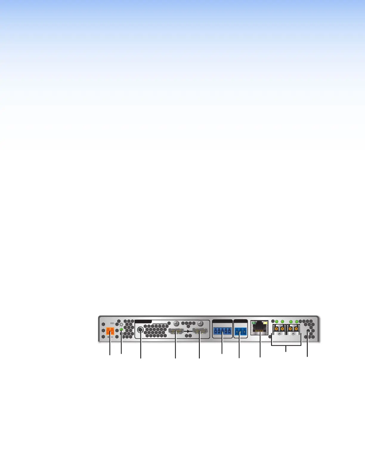
Figure 2. FOX3T201 Transmitter Rear Panel Features
A
Power inlet
F
Control RS-232/IR port
B
Power LED
G
Remote RS-232
C
Audio input
H
LAN Ethernet port
D
HDMI input
I
SFP module and LEDs
E
HDMI Loop Out
J
Reset button
2