FOX3 T 201 Transmitter • Installation and Operation 8
C
Audio input (see figure2 on page5)— Connect an audio input device to the Audio
3.5 mm audio jack.
NOTE: The analog audio input on this
connector is in addition to the digital
audio embedded in the HDMI inputs. See
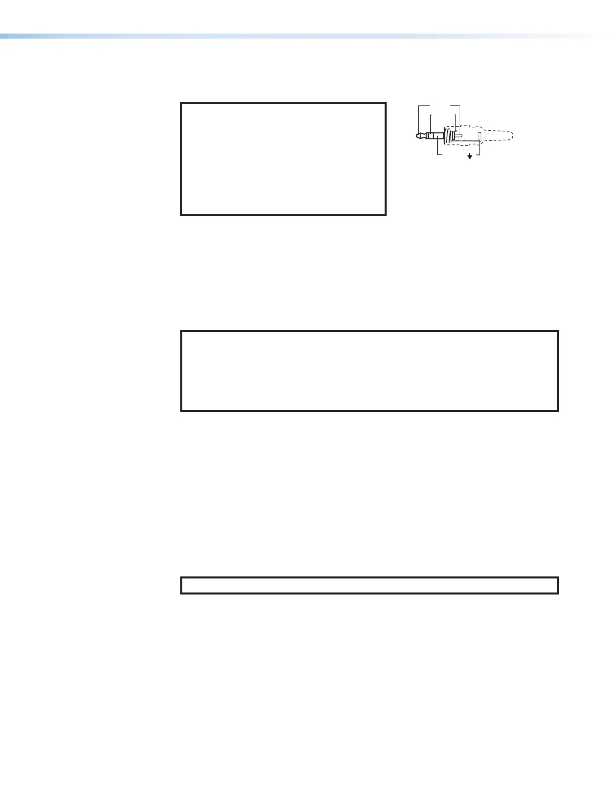
figure4 to identify the connector tip, ring,
and sleeve when making connections for
the transmitter from existing audio cables.
A mono audio connector consists of the
tip and sleeve. A stereo audio connector
consists of the tip, ring, and sleeve.
Sleeve ( )
Ring (
-
)
Tip (+)
3.5 mm Stereo Plug Connector
(balanced)
Figure 4. Audio Wiring Diagram
D
HDMI input — Connect a digital video input to this HDMI port. The transmitter also
accepts embedded digital audio on this port (see HDMI Connectors on page10 to
use the included Extron Lock-It Lacing Bracket).
E
HDMI Loop Out — If desired, connect a local monitor to this HDMI port.
F
Control RS-232 and IR port — Connect a serial RS-232 signal, a modulated
or unmodulated IR signal, or both to this 3.5 mm, 5-pole captive screw port for
bidirectional RS-232 and IR communication (see RS-232 and IR on page11 to wire
the connector).
NOTES:
• To receive responses from the controlled device over RS-232 or IR, two fiber
optic cables must be connected.
• The FOX3 system can pass RS-232 commands and responses at rates up to
115200 baud.
• RS-232 and IR can be active simultaneously.
G
Remote RS-232 port — For serial control of the transmitter, connect a host device,
such as a computer or touch panel control, via the 3-pole captive screw port (see
RS-232 and IR to wire this connector).
H
LAN Ethernet port — Connect the transmitter to an Ethernet LAN or WAN via this
RJ-45 port. Ethernet control allows the operator to configure the transmitter from a
remote location. When connected to an Ethernet LAN or WAN, the transmitter can be
accessed and operated from a computer running a standard Internet browser (see TP
Cable Termination and Recommendations on page11 to wire the connector).
• Link (green) LED — Indicates that the unit is properly connected to an Ethernet
LAN. This LED should light steadily.
• Act (yellow) LED — Indicates transmission of data packets on the RJ-45
connector. This LED should blink as the unit communicates.
NOTE: This is not a pass-through LAN connection
4