FOX3 T 201 Transmitter • SIS Configuration and Control 17
SIS Configuration
and Control
This section describes the remote control operation of the FOX3T201 transmitter,
including:
• Host Control Ports
• Simple Instruction Set Control
• Command and Response Table for SIS Commands
The FOX3 transmitter can be configured using SIS commands, PCS, or embedded web
pages. The FOX3 transmitter can be controlled using SIS commands or PCS. Configure and
control the FOX3 transmitter remotely via a host computer or other device (such as a control
system) by connecting to the rear panel RS‑232 port, LAN port, or the front panel USB port.
Host Control Ports
Rear Panel RS-232 Port
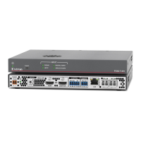
The rear panel serial port (see figure2 on page5) can be connected to a host device
such as a computer running Extron DataViewer, available at www.extron.com. The port
makes serial control of the FOX3 device possible. Use the protocol information listed below
to make the connection.
The protocol for the serial ports is as follows:
• 9600 baud • no parity • 8 data bits
• 1 stop bit • no flow control
Front Panel Configuration USB Port
The front panel mini B USB Configuration port (see figure9,
B
on page12) can be
connected to a host computer for configuration using SIS commands via an SSH client and
IP address 203.0.113.22 on port 22023.
Ethernet (LAN) Ports
The rear panel Ethernet connector (see figure2 on page5) can be connected to
an Ethernet LAN or WAN. Communications between the transmitter and the controlling
device is via an SSH client using port 22023. This connection makes SIS control of the
unit possible using a computer connected to the same LAN or WAN (see TP Cable
Termination and Recommendations on page11 to wire the LAN connector).