IPCP Pro Series • Hardware Features and Installation 13
Front Panel Features
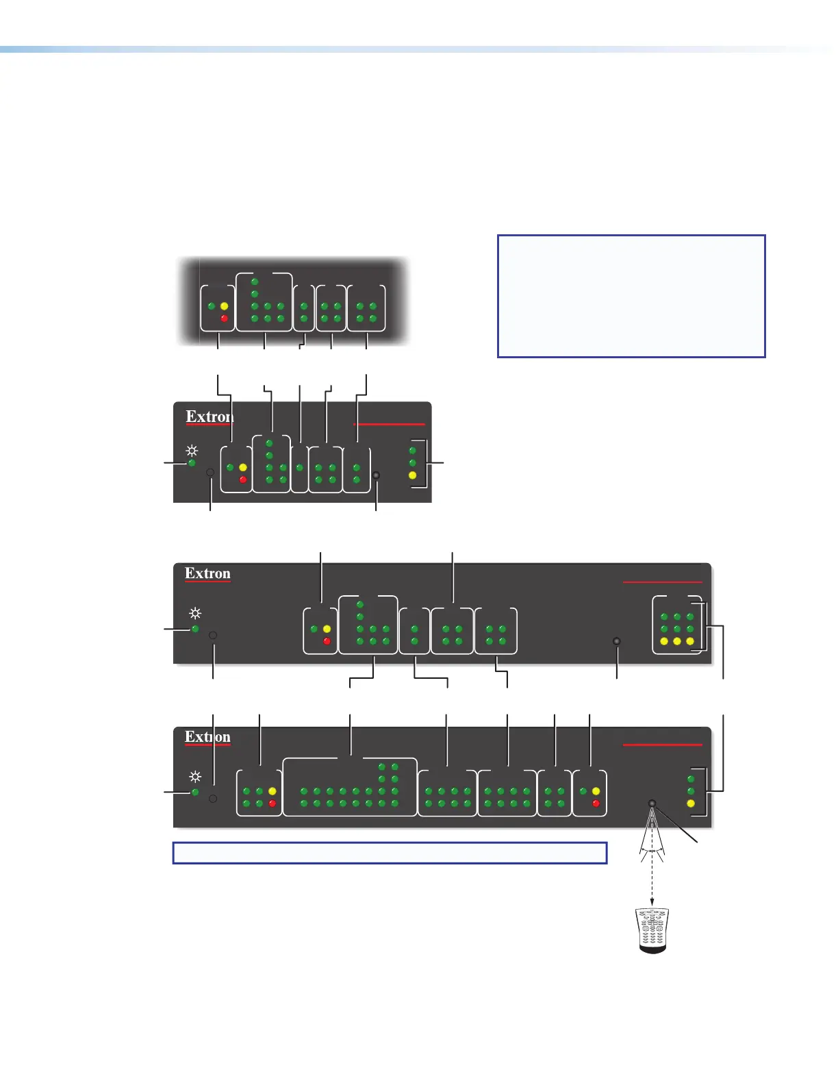
This section shows front panel features and their locations. The quantity and location
of ports and corresponding front panel LEDs differ among IPCP models. However, the
functions of each type of port and their LEDs are identical for all models. Most of the
features and LED indications are described and shown in the Ports, Addressing, and
Connections section paired with the descriptions of the corresponding ports.
R
IPCP PRO 350
1000
LINK
ACT
IR
LAN
12
3
21
LIMIT
R
IR
Tx
Rx
Tx
Rx
RTS
CTS
COM
IR/SERIAL RELAYS FLEX
I/O
S LIMIT
eBUS
SWITCHED
12 VDC
1000
LINK
ACT
IPCP PRO 550
OVER
43 12345678
OVER
5 678
21
3 4
2134
5 678
2134
COM
I/O
RELAYS
IR/S
3
1
4
2
3
1
4
21
2231
S
LIMIT
eBUS
OVER
Rx
CTS
RTS
Tx
S
LIMIT
eBUS
OVER
RTS
1
CTS
Tx
2
Rx
COM
3
1
4
2
I/O RELAYS
1
2
IR/S
R
1000
LINK
ACT
IR
IPCP PRO 250
S
LIMIT
eBUS
OVER
Rx
CTS
RTS
Tx
COM
I/O
RELAYS
IR/S
3
1
4
2
3
1
4
21
2231
NOTE: Numbers adjacent to LEDs correspond to the like-numbered rear panel ports.
Switched
12 VDC
LEDs
COM (Serial)
LEDs
COM
(Serial)
LEDs
IR/Serial
LEDs
IR/
Serial
LEDs
Flex I/O
LEDs
Reset
Button
(recessed)
Reset Button
(recessed)
eBUS LEDs
eBUS
LEDs
IR Receiver
Relay
LEDs
Relay
LEDs
eBUS LEDs
IR Receiver
IR Learning
Angle and
Distance
LAN/
Network
LEDs
Digital I/O LEDs
IR Receiver
LAN/
Network
LEDs
Digital
I/O
LEDs
LED
LED
LED
1 2 3
4 5 6
7 8
0
9
2–12"
(4–30 cm)
15˚ 15˚
IPCP Pro Embedded Control Processor
Without AV LAN
(within another device)
NOTES:
• The Reset button and power LED
for the IPCPPro embedded control
processors are located next to the
rear panel connectors.
• For reset mode information, see
Resetting the Unit on page44.
See the Software-based
Configuration and Control section
starting on page47 and the
Global Configurator Help File and
Toolbelt Help File for information
about Global Configurator and
Toolbelt, which you must use to set
up the unit.
Figure 7. Front Panels: IPCP Pro Series Rack Mountable
Models Without AV LAN
DO NOT DELETE!
Contains link destination
markers to figure 6
and front panel diagram