IPCP Pro Series • Hardware Features and Installation 23
Bidirectional Control and Communication Connections and Features
D
3-pole COM ports, RS-232 only (see figure 14, figure 15, and figure 16 on
page18 through page20) and
E
5-pole COM ports, RS-232/RS-422/RS-485 — Use COM ports for serial control
of a display or other device and to receive status messages from the connected
devices. These ports can send commands from a driver file. RS-232 is the only mode
for the 3-pole ports and is the default mode for the 5-pole ports.
IPCPProSeries serial protocol:
• 300 to 115200 baud (9600 baud = default)
• 8 (default) or 7 data bits
• 1 (default) or 2 stop bits
• No parity (default), even parity, or odd parity
• Flow control support (default = none):
• 3-pole ports: software-only (XON, XOFF)
• 5-pole ports: hardware and software
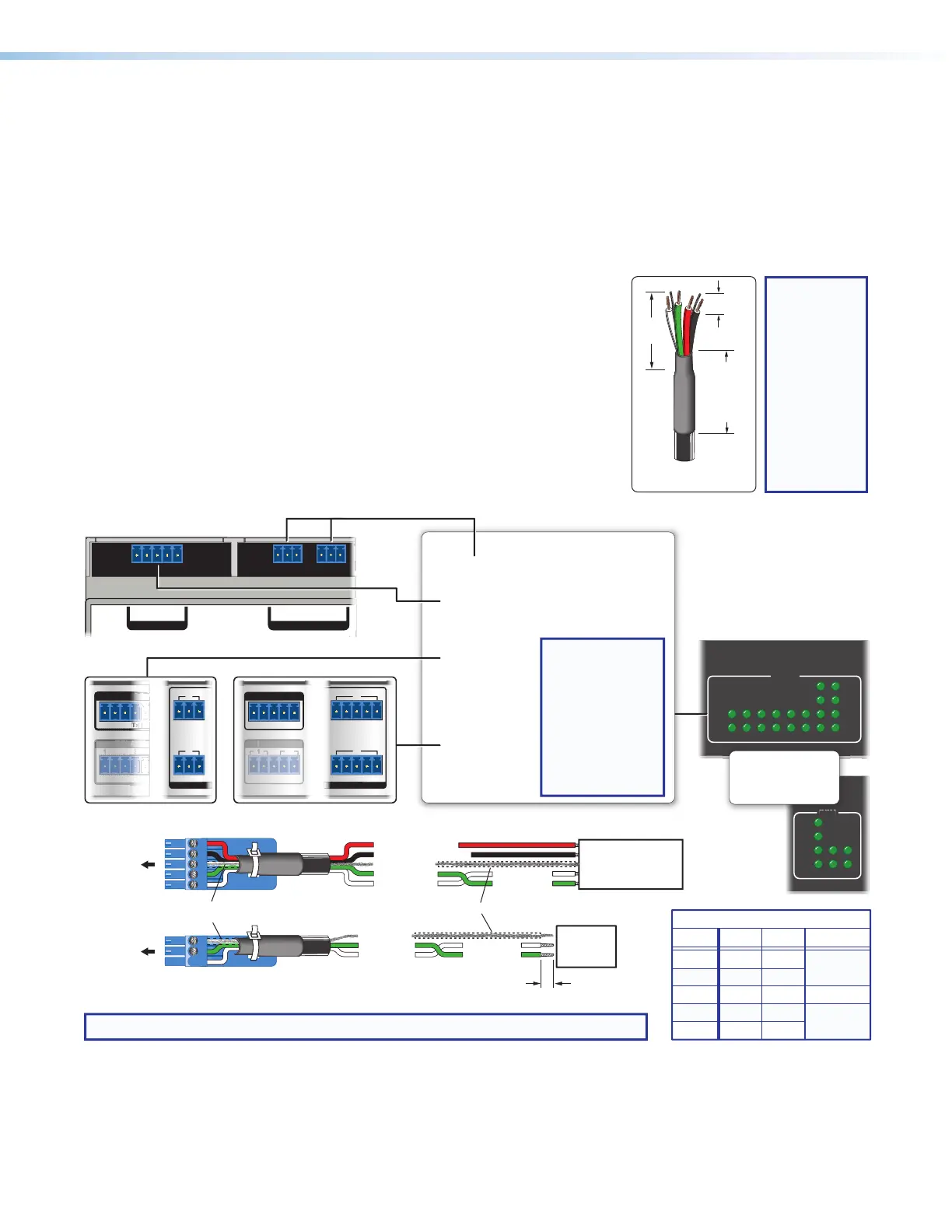
Use the following diagram as a wiring guide to
cable the IPCP to other devices.
GTx Rx GTx Rx
COM 2 COM 3
COM 1
GTx Rx
RTSCTS
G
Tx Rx GTxRxG
RTS
Tx Rx GTxRxG
RTSCTS
CTS
COM 1
GTx Rx
RTS CTS
R
E
IAL
1 7
8
4
GTx Rx Tx Rx
COM 2 COM
Tx
Rx
Tx
Rx
RTS
CTS
COM
12345678
COM
231
Rx
CTS
RTS
Tx
NOTE: If you use cable that has a drain wire, tie the drain wire to ground at both ends.
Projector, Panel
Display, PC, or Other
RS-232, RS-422, or
RS-485 Device
RS-232-
Controllable
Device
Receive (Rx)
Transmit (Tx)
Transmit
Receive
Receive (Rx)
Transmit (Tx)
Ground
Request to send
Clear to send
Transmit
Rx Receive
Tx
CTS
RTS
G Ground
Rx
G
Tx
Strip wires
3/16" (5 mm) max.
Front Panels, Rack Mount Models
5-pole COM
(RS-232, RS-422, RS-485)
3-pole COM
(RS-232)
Serial (COM) Ports
Front/Top Panel, DIN Rail Models
5-pole COM
(RS-232, RS-422, RS-485)
3-pole COM
(RS-232)
Select protocol via software.
COM port default protocol:
• 9600 baud
• 8 data bits • 1 stop bit
• no parity • no ow control
NOTE: The 5-pole
COM ports
support both
hardware and
software ow
control.
The 3-pole COM
ports support
software ow
control only.
To 3-pole
COM port
To 5-pole
COM port
RTS =
Request to Send
CTS = Clear to Send
Tx = Transmitting Data
Rx = Receiving Data
Panels, Rack Mount Models
or or
Heat Shrink
Heat Shrink
Over Shield Wires
RS-232
Tx
Rx
Ground
RTS
CTS
RS-422
Tx-
Rx-
Ground
Tx+
Rx+
RS-485
Ground
5-pole COM Pin Configurations
Data-
(pins 1 & 2
tied together)
Data+
(pins 4 & 5
tied together)
Pin
1 (Tx)
2 (Rx)
3 (G)
4 (RTS)
5 (CTS)
Figure 20. Wiring COM ports for Serial Control
For bidirectional serial communication, the transmit, ground, and receive pins must be
wired at both the IPCPProSeries and the other device. Each projector or other device
3/16"
(5 mm)
Max.
7/8"
(22 mm)
Heat Shrink
on Outer
Jacket to
Inner
Conductor
Transition
Extron
STP 20-2P Cable
TIP:
STP 20-2P
cable, shown
at left, is
recommended
for these
connections.
For best
results,
insulate the
common or
drain wires
using heat
shrink.