IPCP Pro Series • Hardware Features and Installation 24
may require different wiring. For details, see the manual for that equipment or read the
Extron device driver communication sheet, which is included with the drivers.
NOTE: Maximum distances between the IPCP and the device being controlled
are generally up to 200feet (61m) but can vary based on factors such as cable
gauge, baud rates, environment, and output levels from the IPCP and the device
being controlled.
L
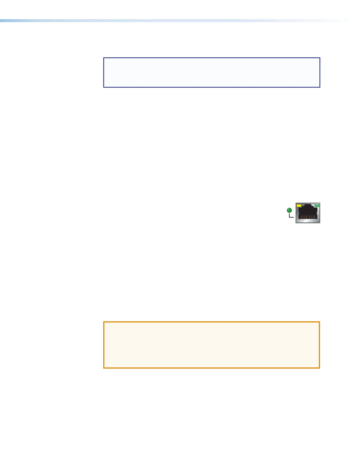
LAN (Ethernet) connectors and LEDs (Ethernet) (see figure 14, figure 15, and
figure 16 on page18 through page20)
and
N
AV LAN connectors and LEDs (Ethernet) —
To connect the IPCP to an Ethernet network (for configuration and control of the IPCP
and the devices connected to it), plug a cable into one of these RJ-45 sockets and
connect the other end of the cable to a network switch, hub, router, or PC connected to
a local network or the Internet. If the IPCP has more than one LAN port or AVLAN port,
the rest of the LAN or AVLAN ports function as simple network switches (a multiport,
unmanaged switch), so that you can connect additional devices to the same network.
AV LAN ports use a separate network interface from that of the main LAN connection
for the unit. Connect AV devices to AVLAN ports in order to create a secure and private
AV Ethernet network and to separate AV communications from the corporate network
traffic.
Power over Ethernet+ (PoE+) output is available on some RJ-45
connectors (AV LAN ports 2 and 3) on some models, such as the
IPCPPro360. PoE+ output allows the unit to provide power to
PoE-enabled AV devices that are controlled by the IPCP.
• Ports labeled “PoE+ Out” can output a maximum of 30watts per port.
• The corresponding Power LED lights when the port provides power.
• Each individual PoE+ port can be configured or programmed to monitor its
connection status and load (power consumption). This allows you to determine
when a PoE supported device is connected to and powered by that port and how
much power is being drawn.
• Power consumption at each PoE+ port is measured in watts, monitored with a
resolution of 0.3watts.
• Schedules can be set up for PoE+ output (via GC or Global Scripter) so that ports
can be turned off automatically to conserve energy.
Additional details are available in the Global Configurator Help file.
ATTENTION:
• Power over Ethernet (PoE) is intended for indoor use only. It is to be connected
only to networks or circuits that are not routed to the outside plant or building.
• L’alimentation via Ethernet (PoE) est destinée à une utilisation en intérieur
uniquement. Elle doit être connectée seulement à des réseaux ou des circuits
qui ne sont pas routés au réseau ou au bâtiment extérieur.
Network Port Addressing:
The default IP addresses and subnet masks for these ports differ depending on whether
or not the unit includes AVLAN ports. You must configure the settings and IP addresses
via Toolbelt. See the help file for Global Configurator or Toolbelt for basic information on
configuration. See the diagrams in this section and see the table on the next page for
default addresses.
Rev. G:
Added reference to AV LAN ports 2 & 3.
Added information on PoE+ port monitoring,
power consumption monitoring, and scheduling.