IPCP Pro Series • Hardware Features and Installation 28
Unidirectional Control and Communication Connections
F
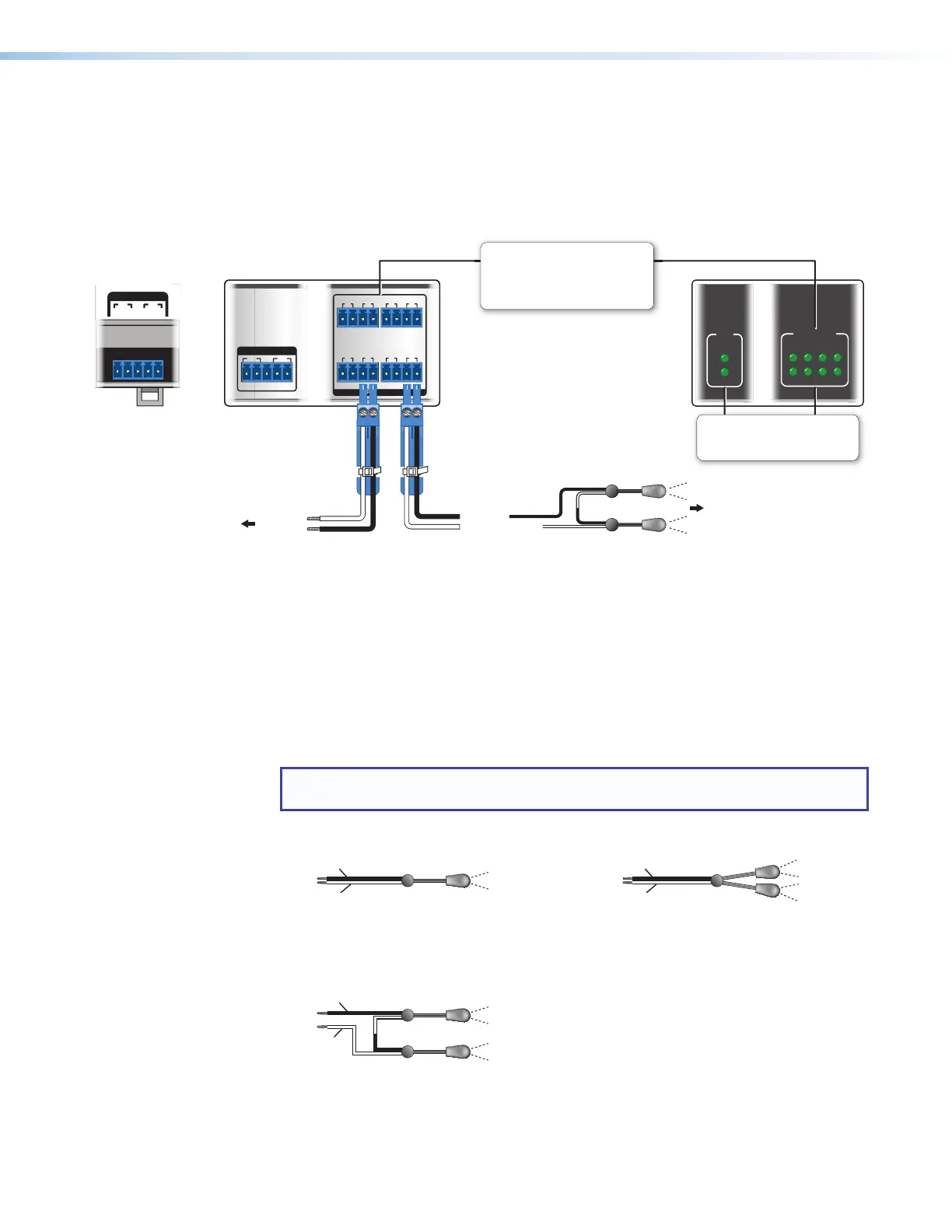
IR/Serial output ports (see figure 14, figure 15, and figure 16 on page18
through page20) — An IPCPProSeries control processor can use infrared signals or
unidirectional RS-232 serial signals to control various devices (up to four per port for IR)
via these ports. Set output signal type (IR or serial) during configuration. The following
figure shows wiring examples.
IR/SERIAL
5678
2134
IR/S
1
2
IR/SERIAL
1
SG
2
SG
IR/SERIAL
SGSG SGSG
SGSG SGSG
1 2
5 6
3 4
7 8
IR/SERIAL
1
SG
2
SG
IR/SERIAL
1
SG
2
SG
Rear Panels, Rack Mount Models Front Panels, Rack Mount Models
Front/Bottom Panel,
DIN Rail Models
To the IR Receiver of a
Projector, Display, or
Source Device
S
G
(-)
(+)
(-)
(+)
(+)
(-)
Ground
IR Output Signal
Unidirectional
IR
IR or RS-232
Output
Ground
To a Projector,
Panel Display, or the
Wired IR Remote or
RS-232 Port of a
IR/Serial LEDs
Light when signals are transmitted
on the corresponding IR/serial port.
IR/Serial Ports
Output options:
• IR (30 kHz to 300 kHz,
with or without carrier signals)
• Unidirectional RS-232
or or
or
Figure 24. Wiring the IR/Serial Ports
Serial control — Connect one of these ports to the serial control receive (Rx) and
ground pins of the device to be controlled. These ports have the same serial protocol
options (see page23) as the COM ports.
IR control — Connect one of these ports directly to the wired IR port of another device.
Alternatively, insert the wires from up to four IR Emitters into an IR port and place the
heads of the emitters over or next to the IR signal pickup windows of the devices. For
wiring, see the following diagrams or the IREmitter Installation Guide (available on
www.extron.com).
NOTE: Each emitter must be within 100 feet (30.4 meters) of the IPCP for best IR
control results.
Installing One Single Emitter Installing One Dual Emitter
Ground (−)
IR Signal (+)
One Single IR Emitter
Ground (−)
IR Signal (+)
Dual IR Emitter
Installing Two Single Emitters
When installing only single emitters, tie them in series as shown below.
(+)
(−)
(−)
(+)
IR Signal (+)
Ground (−)
Two Single IR Emitters