IPCP Pro Series • Hardware Features and Installation 29
G
Relay ports — Relay ports (see figure 14, figure 15, and figure 16 on page18
through page20) provide control for power, screen or projector lifts, window
coverings, and similar items, when trigger events occur.
RELAYS
2143CC
RELAYS
1 2
5 6
3 4
7 8
RELAYS
2143CC
RELAYS
5678
2134
Rear Panels, Rack Mount Models
Front Panels,
Rack Mount Models
Closed
Normally
Open
21C
21C
To Room
Control
Equipment
To Room
Control
Equipment
Normally
Open (2)
Common
Normally
Open (1)
Common
Relays
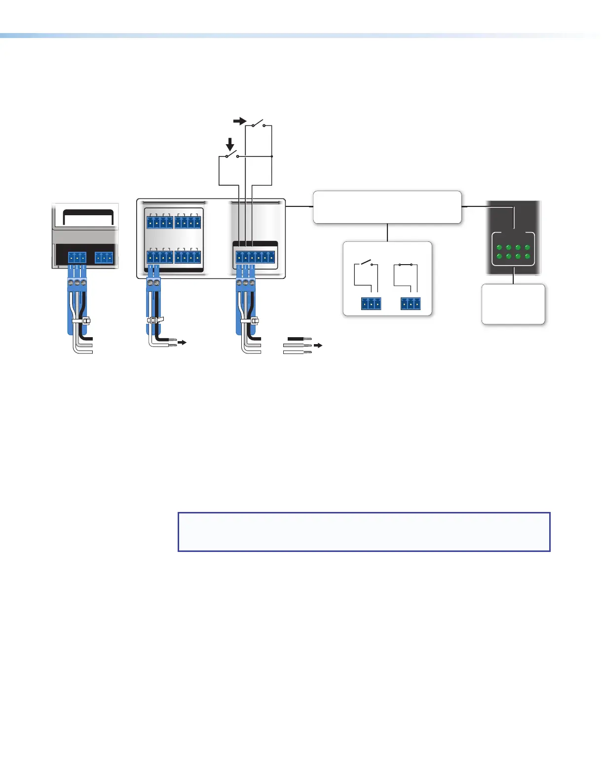
• Connect devices for contact control.
• Do not exceed a total of 24V at 1A for each port.
or
Common
Relay 2
Relay LEDs
Light when the
corresponding relays
are activated (tied to
GND, closed).
Common
Relay 2
All relays
are
normally
open.
ont/Bottom Panel,
N Rail Models
Figure 25. Cabling Relay Ports
These relay contacts may be used to control any equipment as long as the contact
specifications of a total of 24V at 1A are not exceeded for each port. These relays are
normally open by default.
When activated, the open contacts close. They can be set up to operate in one of two
ways:
• Latching (brief or indefinite period contact) (press to close, press to open), or
• Pulsed (timed cycle) (press to close, timeout to open, with automatic repeat).
In pulse mode the default timeout period (hold time) is ½ second (500 ms). Use Global
Configurator to change the length of the timeout period.
NOTE: The pulse function is absolute: it always sets the relay state to closed, times
out (briefly), then opens the contact. It overrides the previously selected setting
(on state, off state, or toggle).