IPCP Pro Series • Hardware Features and Installation 22
B
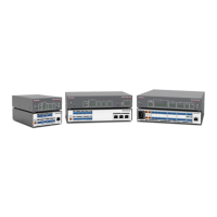
Power input connector (internal power supply) — Connect the IPCP to a
100 to 240 VAC power source here (see figure 14 on page18 or figure 15 on
page19).
R
1.2A MAX
100-240V 50-60Hz
Power Input, Internal Power Supply
• Front panel LED ( ) blinks
during boot-up and remains lit
when the IPCP receives power.
• Connect to 100 to
240 VAC.
Figure 18. Connecting an Internal Power Supply
C
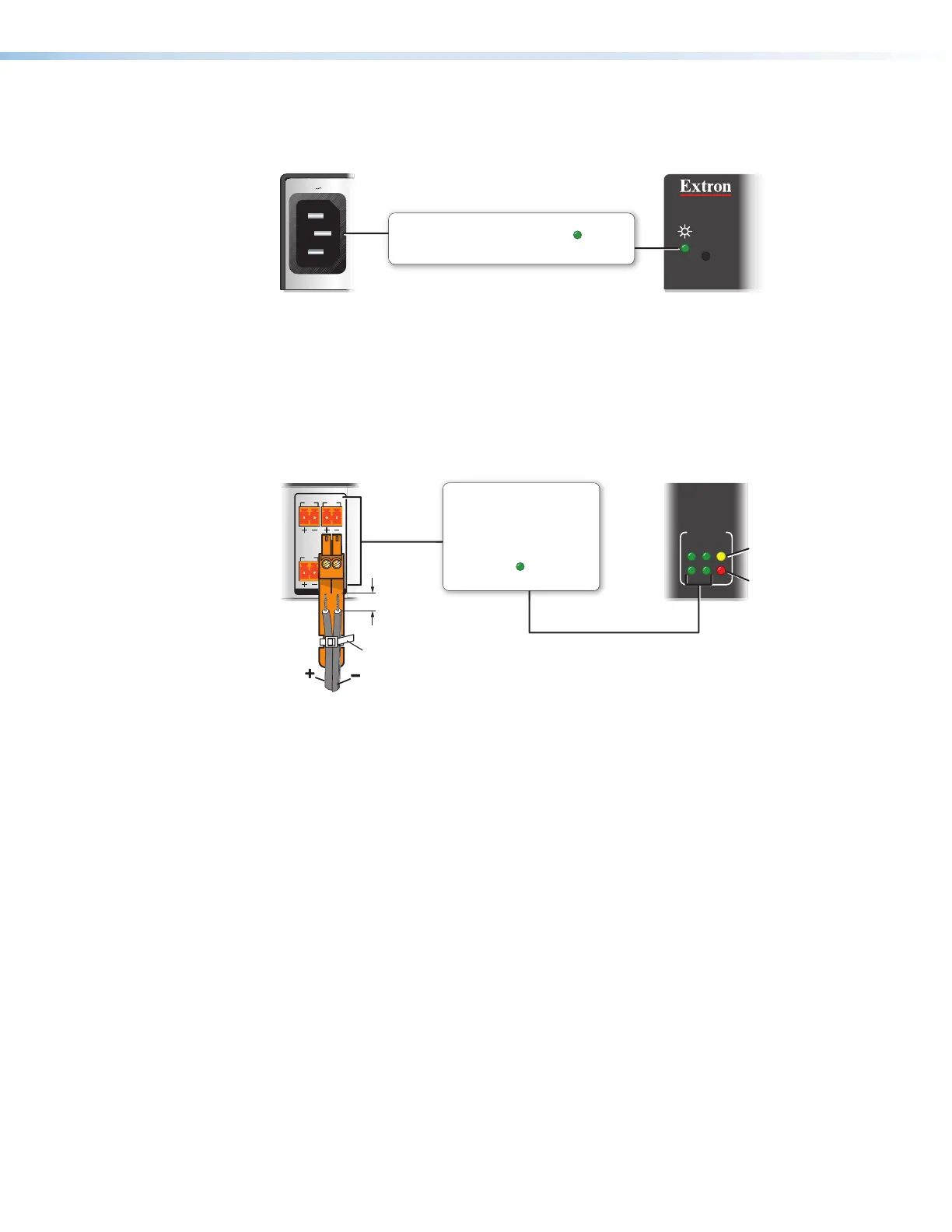
Switched 12 VDC power output ports — These ports (see figure 14,
C
on
page18) provide 12VDC output. For the IPCPPro550 and IPCPPro 555, the four
ports provide up to a combined maximum of 40watts. Once configured, each port can
be separately turned on or off. These ports are monitored continuously for total power
usage (draw).
21
LIMIT
SWITCHED
12 VDC
OVER
43
12 VDC
SWITCHED 12 VDC
40W MAX TOTAL
3 4
1 2
Lights if total power drawn
is 41-46 watts.
Lights if total power drawn
exceeds 47 watts.
Power output shuts off
until the user corrects the
overload.
Switched 12 VDC
Power Output
• Total output for all four ports
combined:
12 VDC, 40 watts (max.)
• Corresponding front panel
green LEDs ( ) light when
power is available at each port.
3/16"
(5 mm)
Max.
Rear
Panel
Front
Panel
Tie Wrap
Figure 19. Switched Power Output Ports and LEDs
• When the total power usage exceeds a threshold of 41watts but is still
below 47watts, the IPCP enters the limit mode, during which the yellow front
panel Limit LED lights. If you have configured the unit to do so, the IPCP can issue a
power overcurrent notice.
• If power usage exceeds a second, higher threshold (47watts), the IPCP enters
overcurrent mode. It turns these ports off, and the red front panel OverLED lights.
If the ports are disabled, the user must disconnect or fix the attached devices to
correct the problem. If the power draw is still excessive, the ports remain off.